Pneumatic
(continued)
12
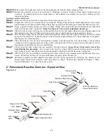
Hook-Ups: Ozone generator-to-vacuum break & vacuum break-to-injector manifold
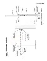
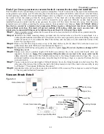
The ClearWater Tech vacuum break provides a positive atmospheric “break” between the ozone injector manifold and the
ozone generator, preventing water from flowing back into the ozone generator should the venturi check valve fail. Under
normal operating conditions, the vacuum break's flapper valve (see Figure 6-3) is closed, allowing the vacuum created by
the venturi to draw the output gas from the ozone generator. If the check valve at the venturi begins to leak or fails
completely, vacuum is interrupted and water will flow toward the ozone generator. With the vacuum break properly
installed between the venturi and the ozone generator, the water will flow down the riser tube (away from the ozone
generator) and out to drain, protecting the ozone generator from potential water damage.
Note: All Teflon® delivery
lines that are secured by a stainless steel compression fittings require a tubing insert (inserts are located in the
Vacuum Break parts bag). This insert will prevent crushing of the tubing, which may create an ozone leak. All
stainless steel compression fittings must be tightened no more than 1-1/4 turns past finger tight.
Step 1:
Select a suitable vertical surface that is accessible and in close proximity to both the ozone generator and the
ozone injector manifold.
Step 2:
Install the two Clic® mounting clamps provided onto the vertical surface so that the vacuum break is in a
vertical position and the drain holes are
below
the level of the ozone generators ozone outlet fitting. One clamp
should be located so it fits around the Riser Tube Elbow, and the other so it fits around the bottom of the
Lower Tee (see Figure 6-3).
Step 3:
Remove the Fill Port Cap located on top of the Riser Tube and fill the Riser Tube with clean water (no
particulate matter) until "Fill Level" line indicated in Figure 6-3.
Step 4:
Re-install the Fill Port Cap, using pliers or a wrench to tighten.
Note:
Do not over tighten as damage to PVC
fittings may occur.
Step 6:
Connect one end of a suitable length of Teflon® ozone delivery line to the ozone outlet needle valve (see
Appendix, Section A).
Notes: The compression fitting ferrules are zip tied to the ozone outlet needle
valve.
Attach the other end of the Teflon® delivery line to the fitting threaded into the Upper Tee. As an
additional backflow prevention measure, loop this length of tubing as high as is practical between the two
connection points.
Step 7:
Connect one end of a second length of Teflon® delivery line to the fitting threaded into the Lower Tee. The
other end of the delivery line will be attached to the fitting located on top of the check valve assembly, in step
6 of Chapter 7, “Start-up and Calibration Procedures.”
Step 8:
Adjustments to the valve on the ozone injector manifold will be necessary. These steps are covered in Chapter
7, “Start-up and Calibration Procedures.”
Vacuum Break Detail
Figure 6-3
Ozone Generator
Ozone Flow
Fill Port Cap
Upper Tee
Ozone Outlet
Ozone Flow
Lower Tee
Riser Tube
Drain Barb
Check Valve Assembly
Overflow Tube
Mounting Clamps
Fill
Level
Riser Elbow
Ozone Injection Manifold
Flapper Check Valve


