


CLARKE
1-41
ENCORE MAX
+
+
+
+
+
+
+
+
-
-
-
-
-
-
-
-
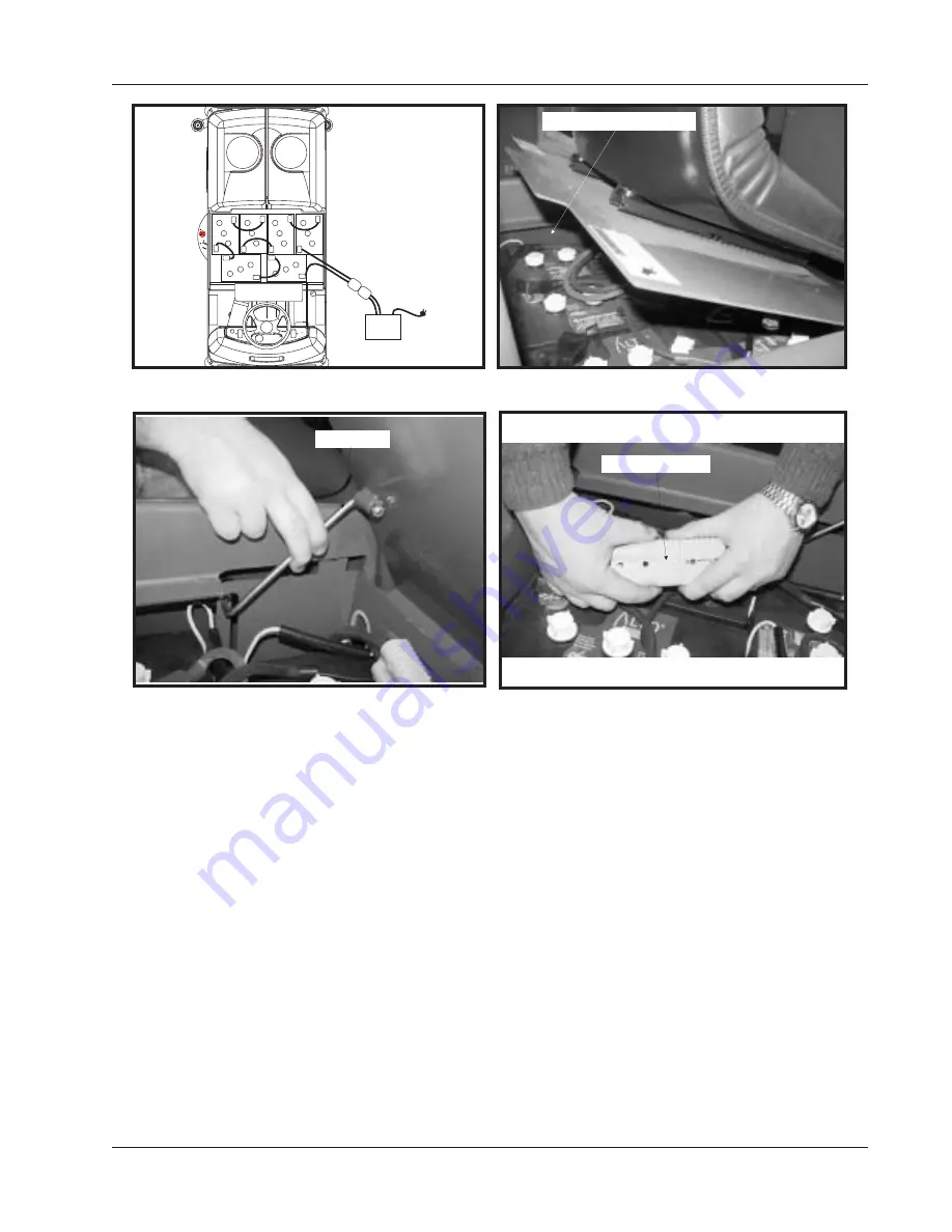
BATTERY
CHARGER
SAFETY LATCH
CONNECT BATTERIES
BATTERY CHARGING INSTRUCTION
When the batteries are disconnected (i.e. charging, replacement), the microprocessor needs to be reset by
turning the key switch on and raising the brush deck. When the red light comes on steady the batteries can
be charged.
1.
Lift seat cover, make sure safety latch is secure in notch.
2.
Insert charging plug into battery receptacle.
3.
Plug power cord into proper AC source.
4.
Follow the charging instructions provided on the charger.
5.
Maintain electrolyte level in batteries, check after charging. Add distilled water as needed.
Fig. 48
Fig. 49
Fig. 50
LIFT SEAT TO ACCESS BATTERIES
Fig. 51
MAINTENANCE
Summary of Contents for ENCORE MAX
Page 2: ...1 2 CLARKE ENCORE MAX NOTES...
Page 16: ...1 16 CLARKE ENCORE MAX SPECIFICATIONS...
Page 53: ...CLARKE 1 53 ENCORE MAX ELECTRICAL SCHEMATIC PG 53 REMOVE INSERT 11 X 17...
Page 54: ...1 54 CLARKE ENCORE MAX WIRE HARNESS CONNECTIONS PG 54 REMOVE INSERT 11 X 17...
Page 55: ...CLARKE 1 55 ENCORE MAX NOTES...
Page 57: ...CLARKE 1 57 ENCORE MAX WIRE HARNESS ROUTING PG 57 Ref 71716 3 REMOVE INSERT 11 X 17...
Page 58: ...1 58 CLARKE ENCORE MAX 11 x 17 WIRE HARNESS CONNECTIONS SPRAY WAND PG 58...