background image

Printer Operation

40

2

Top Menu

Sub Menu

Default

Menu

Remarks

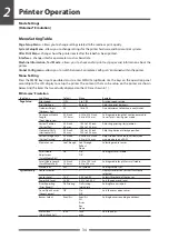
RS-232C Stop bit

[RS-232C Stopbit]

1 bit

1 bit

2 bits

Setting the stop bit for the serial interface.

RS-232C X-ON

On Yes

On Yes

Off No

Selectively setting the X-ON flow control of 

the serial interface.

IEEE1284

On

On

Off

Setting both direction of the Centro Interface.

Web Monitor

Auto

Auto

On

Off

Selecting the web monitor function.

Network Address

0.0.0.0

0.0.0.0 to

255.255.255.255

Setting fixed IP address of the LAN board.

Subnet Mask

0.0.0.0

0.0.0.0 to

255.255.255.255

Setting fixed subnet mask value of the LAN 

board.

Gateway address

0.0.0.0

0.0.0.0 to

255.255.255.255

Setting fixed default gateway address of the 

LAN board.

BOOTP

Off

On

Off

Setting the BOOTP of the LAN board.

DHCP

Off

On

Off

Setting the DHCP of the LAN board.

USB Device Class

[USB Device Clas]

Printer

Printer

VCOM

Selects the USB device class.

USB VCOM Protocol

[VCOM Protocol]

Auto

Auto

DTR

X-ON

Selects the protocol (flow control) when 

operating USB VCOM.

Machine 

Information

[Machine Info]

Model Number

CL-S***

Displays the model name.

Boot Version

*.*

Displays the boot version.

ROM Version

********

Displays the ROM version.

ROM Date

**/**/**

Displays the date the ROM was prepared.

ROM CheckSum

****

Displays the check sum of the ROM.

Head Check

OK

NG

Displays the results of the head check.

Print Counter

****.*** km

Displays the print counter.

Service Counter

****.*** km

Displays the service counter.

Cut Counter

Displays the cut count.

Sensor Monitor

*.* V

Displays the sensor level.

Option Interface

[Option I/F] 

None

LAN

Displays the presence/absence of the optional 

interface.

Test Mode

Print Pattern

Current Config Current Config

Global Config

Sample

Executes the test pattern.

Head Check

No

Yes

No

Executes head check.

Factory Default

No

Yes

No

Initializes the set values of the configuration 

set to the state when the unit was shipped 

from the factory.

Hex Dump 

No

Yes

No

Sets the hex dump mode.

Serial Monitor

Displays the state of the serial interface.

Auto Calibration

[Auto Cal]

See Through See Through

Reflect

Executes the calibration of the sensor.

Sensor Monitor

See Through See Through

Reflect

Displays the level of the sensor.

Global

configuration

[Global Config]

Config Set 1

Config Set 1

Config Set 2

Config Set 3

Sets the Config Set.

Note:

  To restore factory default settings, turn on printer power while pushing the MENU and PAUSE keys 

simultaneously, then press the FEED key and the STOP key sequentially.

Mode Settings
[Zebra® Emulation]

Summary of Contents for CL-S700DT

Page 1: ...Direct Thermal Barcode Label Printer CL S700DT USER S MANUAL...

Page 2: ...nfirmation of Carton Contents 10 Part Names and Functions 11 Connection to Power 17 Driver Installation 17 Connection to a Computer 18 Chapter 2 Printer Operation Power ON OFF 19 Normal Operating Mode...

Page 3: ...oading The Hi Lift metal print head mechanism opens so that it is completely clear of the media path so that the paper can be loaded without any part of the printer in the way Easy Printer Control and...

Page 4: ...S This equipment has been tested and found to comply with the limits for a Class A digital device pursuant to Part 15 of the FCC Rules These limits are designed to provide reasonable protection agains...

Page 5: ...to connect this device to computers Any changes or modifications not expressly approved by the grantee of this device could void the user s authority to operate the equipment ETAT DE CONFORMITE EMI A...

Page 6: ...cord is used with this product make sure that the total of the ampere ratings on the products plugged into the extension cord do not exceed the extension cord ampere rating Also make sure that the tot...

Page 7: ...missions or misprints We are not liable for any problems resulting from the use of optional products and consumable supplies other than the designated products contained herein Do not handle disassemb...

Page 8: ...printer Do not place the printer where chemical reactions occur such as in laboratories or where air is mixed with salt or gas Do not use a power voltage or frequency other than those specified Do no...

Page 9: ...them Do not use or store the printer near fire excessive moisture in direct sunlight near an air conditioner or heater or other source of unusually high or low temperature or humidity or excessive dus...

Page 10: ...ttached paper by carefully peeling from the plastic case Retain the tape should you need to transport the printer again A further piece of packing paper is inside the mechanism and you can remove this...

Page 11: ...could slam shut possibly causing injury Be careful of the edge of the cover when the cover is opened It may cause injury or property damage Be careful of the edges of the metal plates as injury or pro...

Page 12: ...ions 2 1 1 Media holder guide This guide is moved horizontally to match the media size The guide can be sliding it from the holder bar 2 Media holder bar The media is supported by the media holder bar...

Page 13: ...h adjustment knob It is adjusted to match the width of the media 4 Media thickness adjustment indicator 5 Head open lever The head unit can be raised to install media by pushing this lever It locks th...

Page 14: ...tion This sensor is more accurate for small labels as it is closer to the print head 4 Left media guide This is a fixed part of the printer The left side of the media labels tags as viewed from the fr...

Page 15: ...or flashes when the printer is in an alarm or error status orange 4 FEED key This key feeds the media to the top of the next label or form 5 PAUSE key This temporarily stops printing 6 STOP key This...

Page 16: ...ial transmission of data from a host computer 3 USB interface This receives USB transmission of data from a host computer 4 Warm air opening It allows warm air to vent from the printer Be sure not to...

Page 17: ...ree pronged plug Otherwise static electricity may be generated and there will be danger of electric shock Driver Installation The computer may automatically detect the presence of the new printer when...

Page 18: ...mputer Connect one end of the interface cable to the interface 222 connector on the back of the printer and secure it with locks or locking screws where available Connect the other end of the interfac...

Page 19: ...easy access during normal operation It is in the recess underneath the control panel so it cannot be accidentally operated by mistake The POWER LED is lit 222 Power Switch Operation Panel POWER ERROR...

Page 20: ...continuous media has been designated a fixed quantity is fed then feeding stops When the TEAR OFF setting is effective feeding stops when the media has been fed to the TEAR OFF location When the opti...

Page 21: ...ture low temperature abnormality Flashing Error Head Cold PF motor temperature abnormality Flashing Alarm PFMotor Hot Fan motor malfunction Flashing Error Fan Lock Cutter motor temperature abnormality...

Page 22: ...and notches of tag media Reflective sensor Detects the black mark A C I I G H D K K F E B J L N M Notch detection Black mark detection Use of media gap sensor Printable area Size of media Use of black...

Page 23: ...0049 H Media thickness 0 06 0 0025 0 25 0 01 I Right end of notch 8 3 0 32 11 0 43 J Left end of notch 0 0 4 7 0 19 K Notch length 2 54 0 10 17 80 0 70 L Right end of black mark 15 00 0 59 M Left end...

Page 24: ...open lever Head unit Firstly slide the two black plastic parts of the media holder 222 assembly together Ensure correct alignment of the guide with the bar as it can only be installed in one direction...

Page 25: ...dia guide 2 locations 666 align the right movable media guide with the media width and lower the damper arm which loosely holds the media in position Fixed media guide Damper arm Movable media guide L...

Page 26: ...l media Turn on printer power while pushing the STOP key If the POWER LED is lit and the LCD indicates Hex Dump Mode and Label Media release the STOP key and then the printer enters HEX DUMP mode When...

Page 27: ...ED key After it enters TEST MODE and it prints then printing stops To repeat printing press the FEED key once more Media Adjustments Using the Self Test Print shown above you can make adjustments to t...

Page 28: ...ate the menu Refer to the four small arrows in the centre of the keypad rather than the names of the keys FEED key Shift Change The key Feed key goes up the menu system or selects a higher value MENU...

Page 29: ...NU PAUSE On Line Ready Main Menu Page Setup Exit Enter The current main menu is displayed The following are the functions of each key key displays the previous menu item key displays the next menu ite...

Page 30: ...ond item within Page Setup Page Setup Print Darkness Exit Enter Displaying the set value of Print Darkness 444 Press the key and the value 12 the currently set value is displayed Darkness 12 Exit Ente...

Page 31: ...effect The printer will offer to do this when needed by displaying the following message after saving the settings The screen shown on the right will be displayed when Save Settings Yes Save is selec...

Page 32: ...ll Media Adjustment Off Small Media Length 1 00 inch Symbol Set PM System Setup Menu Sensor Level 1 7 V Paper End Level 2 80 V Error Reporting On Printing Cover Open Sensor Off Buzzer Select On Metric...

Page 33: ...ig 1 Config 2 Config 3 PageSetup Menu Print Speed 5 8 7 Print Darkness 18 12 12 Darkness Adjust 00 00 00 Continuous Media Length 04 00inch 04 00inch 04 00inch Vertical Position 0 00inch 0 00inch 0 00i...

Page 34: ...of sensor that is currently selected Sensor Level 1 4 V 0 0 V to 3 0 V Selects threshold of the sensor Paper End Level 2 80 V 0 01 V to 3 00 V Sets the paper end level Error Reporting Error Report On...

Page 35: ...Select Function Sel Tear Off Tear Peel On Cut On Selects the operation when the AutoConfigure is set to Off Designates the paper position based on each option The operation of this device is enabled d...

Page 36: ...X ON On Yes On Yes Off No Selectively setting the X ON flow control of the serial interface IEEE1284 On On Off Setting both direction of the Centro Interface Web Monitor Auto Auto On Off Selecting th...

Page 37: ...ues of the configuration set to the state when the unit was shipped from the factory Hex Dump No Yes No Sets the hex dump mode Serial Monitor Displays the state of the serial interface Auto Calibratio...

Page 38: ...s level of sensor that is currently selected Sensor Level 1 4 V 0 0 V to 3 0 V Selects threshold of the sensor Paper End Level 2 80 V 0 01 V to 3 00 V Sets the paper end level Error Reporting Error Re...

Page 39: ...t at the rear end of sheets 1 to n 1 when the number of copies n and the rear end of the final page of single sheet and the copy is backfeed Peel Wait Delay 0 1 sec 0 1 to 2 0 sec Sets the Peel Wait D...

Page 40: ...on Displays the ROM version ROM Date Displays the date the ROM was prepared ROM CheckSum Displays the check sum of the ROM Head Check OK NG Displays the results of the head check Print Counter km Disp...

Page 41: ...MX detected Switch emulation No Yes By selecting Yes the printer will reboot and automatically switch to Datamax emulation DM4 DMI DPP The printer will return to the On Line Ready status if No is sele...

Page 42: ...PAUSE After Sensor Cal Mode lights up release the keys to change 222 the printer to sensor adjustment setting mode POWER ERROR Sensor Cal Mode See Through Quick Sensor Selection Method Transparent Re...

Page 43: ...media If the Pause Key is pressed then released while the MENU key 333 is continually pressed the sensor is automatically adjusted Sensor Cal Mode Executing MENU PAUSE Press Release Hold When automati...

Page 44: ...ead Black mark Label Liner media Bottom sensor If the Pause Key is pressed then released while the MENU key 333 is continually pressed the sensor is automatically adjusted Sensor Cal Mode Executing Wh...

Page 45: ...test print 222 When using thick media tags or other media Looking in at the media thickness check window reset 111 the printhead position so that it comes to the center line middle of the three lines...

Page 46: ...ad must be closed Make fine adjustments by checking the self test print 222 When the print on right side is too light Move the mark white to the right side by turning the media width adjustment knob c...

Page 47: ...s particularly important to clean the thermal printhead after printing on thermal media for long periods which will guarantee the print quality and extend the life of the thermal printhead Note Always...

Page 48: ...ected to 4 Check to make sure power is supplied to the outlet If there are any problems make sure power is supplied to the building Or find out if a power failure has occurred 5 Is the main fuse in th...

Page 49: ...dial 6 Is the printer s head pressure balance correct for the width of the media that is used 6 Adjust the thermal printhead pressure with the media width adjustment dial The printing position changes...

Page 50: ...Min media width 25 4 mm 1 00 inch Min label width 7 62 mm 0 30 inch Min label pitch 3 6 35 mm 0 25 inch Max media thickness 0 254 mm 0 01 inch Max media length 812 8 mm 32 inch Min media length 6 35 m...

Page 51: ...ws 3 1 Latin 5 Control language Conforms to Datamax programming language 7 and Zebra programming language 8 Outline of electronic devices CPU 32Bit RISC CPU ROM Standard equipment FLASH ROM 4MBytes Us...

Page 52: ...uick start guide Head cleaner Power cord Media holder bar and Media holder guide Option Auto cutter unit Peeler unit Parallel interface Ethernet interface and Rewinder kit 1 2 Options can be separatel...

Page 53: ...D SUB 25PIN Signal line and pin arrangement Pin No Signal code Signal name Function 1 FG Protective grounding Protective grounding 2 TXD Transmitted data Signal line that transmits data from the print...

Page 54: ...tes available 16K bytes XON XOFF Receive buffer 1024 bytes 128 bytes DTR Protocol Conditions when the DTR signal is Ready High All the following conditions are satisfied The receive buffer is 128 byte...

Page 55: ...P mode permits bi directional asynchronous data transmission and thanks to its interlock handshake it does not require the timing necessary with compatible mode Signal level IEEE1284 standard Signal l...

Page 56: ...Busy L H PError L H Select H L nFault H L Error other than paper end Head open Other Busy L H PError L unchanged Select H L nFault H L Conditions for Busy Receive buffer full Data being read Error Co...

Page 57: ...5 sec Note If the Init signal does not have width of 10 to 15 sec or more it cannot act as an Init signal If it is lower the Init signal is ignored BUSY starts up when the Init signal is perceived Rel...

Page 58: ...cification Transmission speed Compatible with 12Mbps full speed transmission Receive buffer 16K bytes Connector DUSB DUSB BRA42 T11 DDK Signal line and pin arrangement Pin No Signal code Signal Functi...

Page 59: ...ment Method Remove the screws 2 of the interface cover then pull the 111 interface cable towards you When you do this be careful not to perform any unreasonable operations that will damage the connect...

Page 60: ...terface board into the printer so that the 333 connecting cable does not catch on the printer then use the screws 2 that you removed to anchor the bracket Interface Board Screw Rear Side Connecting th...

Page 61: ...ta por la Directiva 2002 96 CE sobre residuos de aparatos el ctricos y electr nicos RAEE vigente nicamente en la Uni n Europea Sp Se desiderate gettare via questo prodotto non mescolatelo ai rifiuti g...

Page 62: ...51 Staines Road D 73728 Esslingen Feltham Middlesex TW14 8PA Germany United Kingdom Tel 49 0 711 3906 420 Tel 44 0 20 8893 1900 Fax 49 0 711 3906 405 Fax 44 0 20 8893 0080 http www citizen europe com...

Reviews: