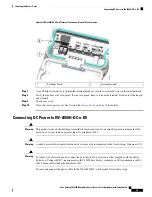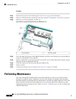
Figure 25: IW-6300H-DCW-x-K9 Internal Ground and Terminal Block Location
Internal ground
2
Terminal block
1
Step 7
Use a Phillips screwdriver to tighten the terminal block set screws to secure the wires in the terminal block.
Step 8
Verify that no bare wire is exposed. If wire is exposed, remove it from the terminal block, adjust the length,
and reinstall.
Step 9
Check your work.
Step 10
Close the access point cover. See
Closing the Access Cover, on page 34
for details.
Connecting DC Power to IW-6300H-DC-x-K9
This product relies on the building’s installation for short-circuit (overcurrent) protection. Ensure that the
protective device is rated not greater than:5 A. Statement 1005
Warning
A readily accessible two-poled disconnect device must be incorporated in the fixed wiring. Statement 1022
Warning
To reduce risk of electric shock, connect the unit only to DC power source that complies with the Safety
Extra-Low Voltage (SELV) requirements in IEC 60950 based safety standards or ES1 requirements in IEC
62368 based safety standards. Statement 1033
Warning
To route and connect the power cable to the IW-6300H-DC-x–K9 model, follow these steps:
Cisco Catalyst IW6300 Heavy Duty Series Access Point Hardware Installation Guide
45
Installing the Access Point
Connecting DC Power to IW-6300H-DC-x-K9


