Procedure
Step 1
Open the access point cover. See
Opening the Access Cover, on page 33
for instructions.
Step 2
Ensure a 6 AWG ground wire is connected to the access point (see
Grounding the Access Point , on page 38
Step 3
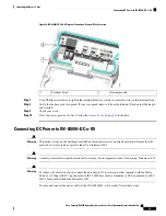
Route the power cable through the 1/2-NPT port.
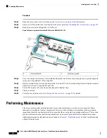
Figure 26: Connecting Internal Ground and DC Power for IW-6300H-DC-x-K9
Internal ground
2
Terminal block
1
Step 4
Use a wire stripper tool to remove the insulation from each wire. Remove only enough wire to provide adequate
crimp on to ring terminals (Cisco supplied).
Step 5
Remove terminal strip screw and square washer. Connect DC line to terminal strip location. Tighten terminal
strip screws to secure ring terminal and wire.
Step 6
Secure DC input cord to wire tie anchor adjacent to terminal strip.
Step 7
Check your work.
Step 8
Close the access point cover. See
Closing the Access Cover, on page 34
for details.
Performing Maintenance
The access point requires minimal periodic or preventive maintenance as it has no moving parts, filters,
lubricants, or mechanical contact components. However, when installed in a hazardous location, periodic
inspections should be conducted in order to ensure that the access point is operating satisfactory. This section
provides information about performing maintenance on an access point installed in a hazardous location.
Additional maintenance information can be found in
and the Troubleshooting
a Mesh Network Guide.
Cisco Catalyst IW6300 Heavy Duty Series Access Point Hardware Installation Guide
46
Installing the Access Point
Performing Maintenance


