2-8
J Series 2.0, 2.4, and 3.0 kW Setup Guide
020-100751-01 Rev. 1 (10-2011)
Section 2: Installation and Setup
3.
Center the image in the lens:
Holding a piece of paper at the lens surface, adjust offsets as necessary until
the image is centered within the lens perimeter. A full white field works best for this.
4.
If necessary, center the image on the screen:
If the projector is mounted off center to the screen axis,
then offset the lens as much as required. Aim the projector over slightly towards the center of the screen,
but use caution when doing so, as too much tilt will cause excessive keystone distortion. Lens offset will
not.
5.
Re-check side-to-side leveling:
With the framing pattern on screen, double-check projector leveling
so the
top edge
of the image is parallel to the top edge of the screen.
6.
Throw Distance:
Ensure the projector is positioned in the throw distance range for the particular lens.
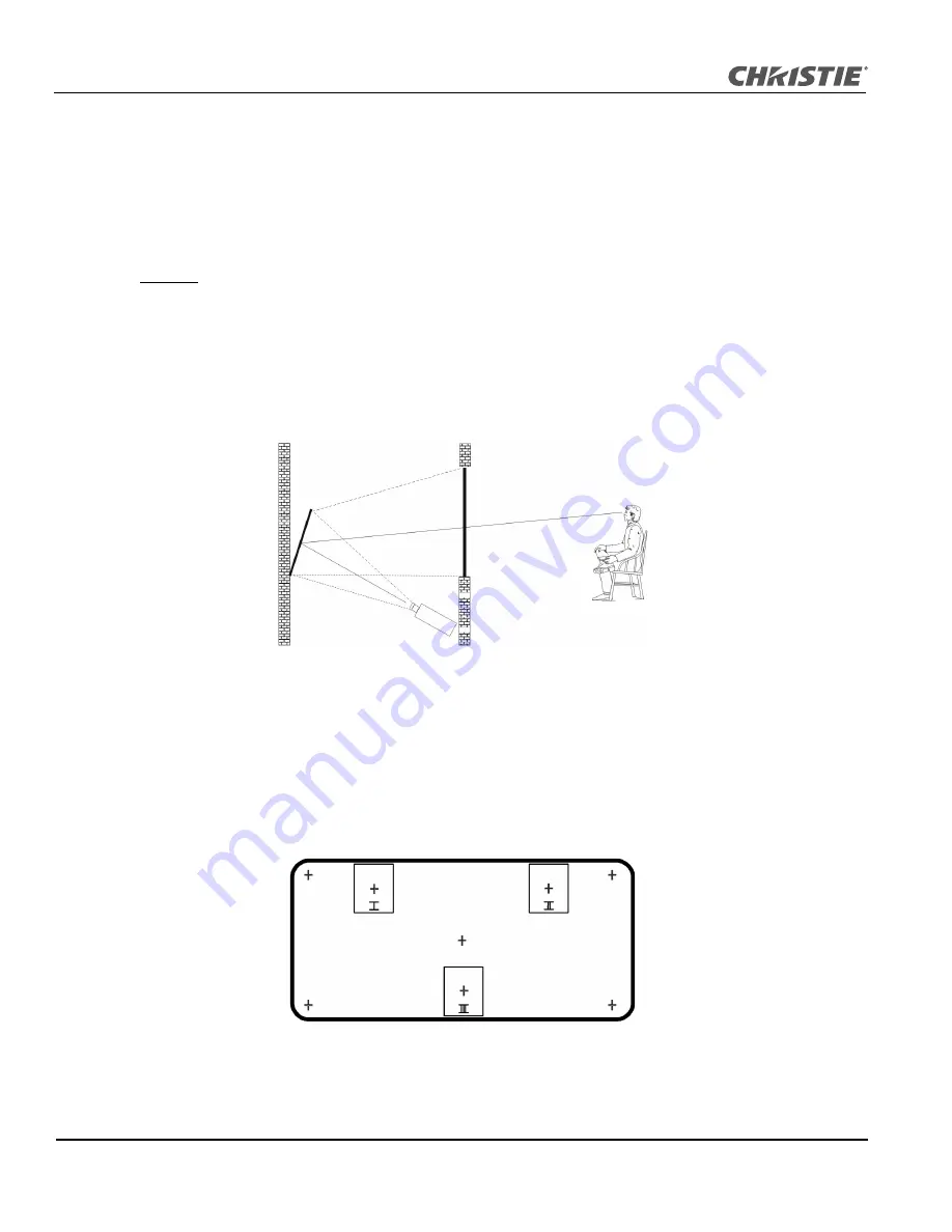
Folded Optics
In rear screen applications where space behind the projector is limited, a mirror may be used to fold the optical
path, see
Figure 2-9
. The position of the projector and mirror must be accurately set - if considering this type of
installation call your dealer for assistance.
F
IGURE
2-9
2.2.3 Advanced Optical Alignment
Boresight Alignment Procedure
1. Display the Boresight Test Pattern by pressing the
T
EST
key on the remote keypad or use the built-in
keypad and press the soft key that displays Test on the LCD display, then
U
P
A
RROW
K
EY
to cycle to
Boresight, then Enter, see
Figure 2-10
.
F
IGURE
2-10
Summary of Contents for J Series
Page 1: ...J Series 2 0 2 4 and 3 0 kW S e t u p G u i d e 020 100751 01 ...
Page 2: ......
Page 3: ...J Series 2 0 2 4 and 3 0 kW S e t u p G u i d e 020 100751 01 ...
Page 22: ......
Page 42: ......
Page 50: ......
Page 56: ......
Page 59: ......


