


INST No. INE-403-0P0
−
11
−
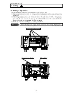
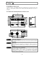
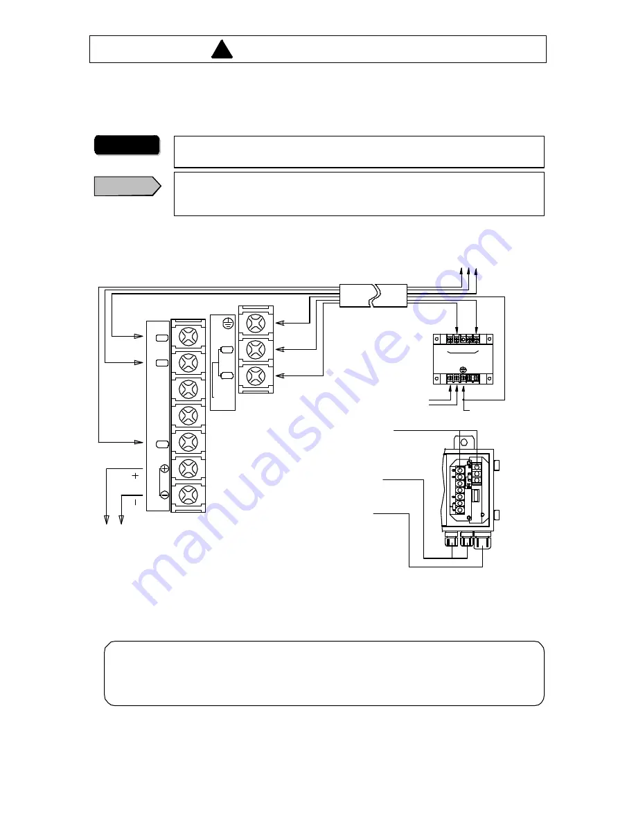
4.1 Connections
The terminal board is accessible by opening the door of the detector unit. Lead in cables
through a small sized cable inlet at the lower part and connect them to terminals. Lead in the
exclusive cable IR-WERT
through the large cable inlet.
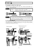
4.2 Layout of connection cable
For connection of cables, be careful of the following points.
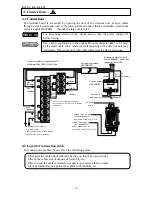
4. Connections
For preventing electric shock, make sure to turn the power supply off
before wiring.
Wa rn i n g
C a u t i o n
Use a cable conforming to the applicable outer diameter (
φ
4.5 to 6.5mm)
of the small cable inlet; otherwise waterproofing of the detector unit may
deteriorate. Tighten the nut at the cable inlet securely after connections.
・
Separate the cables from induction heating oscillator and power lines.
・
Keep the cables free of deposit of water, oil, etc.
・
Don’t bend the cables extremely or apply any excessive force to the m.
・
For permanent layout, protect the cables with conduits, etc.
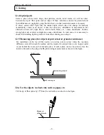
SA
(Black)
SB
(White)
SG
(Brown)
G *1
(Green)
P+
(Red)
P-
(Blue)
P-
(Blue)
P+
(Red)
G
(Green)
V+
V-
LN
24V DC
Ground
Power supply
(IR- WEP)
100- 120V AC
200- 240V AC
Terminal
board
Cable inlet (small):
Outer diameter of
appl icable cabl e
Ø
4.5 to
Ø6
.5
Cable inlet (large):
[For IR- WERT]
Outer diameter of
applicable cable
Ø8
.5 to
Ø10
.5
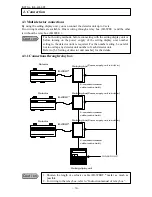
Connection cable
(IR-WERT)
Communication output
for IR-GMEG1, personal
computer and PLC.
Communication output RS- 485
(Optional:RS- 232C, RS- 422A)
*1:Don't connect this cable usually,
but connect it, i f the unit is interfared
wi thnoises.
SA
SB
SG
OUT
Measured value output :
4 to 20mA DC
Load resistance:Lower than 500
Ω
(Optional:R S- 232C, RS- 422A)
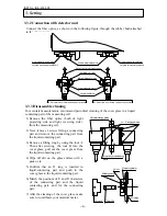
P+
P-
24VDC
1.5A
SUPPLY
!


