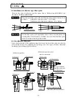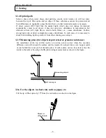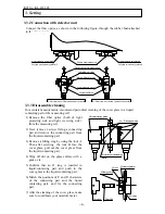
INST No. INE-403-0P0
−
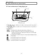
3
−
3.1 Setting of dipswitches
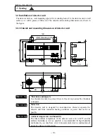
Set the internal dipswitches before installation of the detector unit.
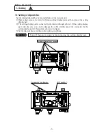
1) Open a door, remove 4 screws for fixing a setting display part and then remove the setting
display part.
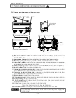
2) The setting display part is connected to the interior through cables. Lift the setting display
part with due care so as not to damage the cable and disconnect the connector for the
setting display part at the position shown in the figure.
3) Set the dipswitches according to the working conditions.
3. Setting
Turn off the power supply before removing the setting display part.
W a rn i n g
Loosen these four screws
CH
DATA
△
△
▽
SEL
ENT
CH/
□
DIP switch 1
Connector for display
!


