background image

[DB600] General instruction manual 


- 138 - 

9


Appendix 


9-1


Specifications 


Input specifications 

Input signal: 


Thermocouple 

B, R, S, N, K, E, J, T, U, L, WRe5-WRe26, 

W-WRe26, Platinel II, PtRh40-PtRh20, 

Au-Pt 

DC voltage 

±20mV, ±100mV, ±5V, ±10V 

Resistance 

thermometer 

Pt100, JPt100, Pt50 

Measuring range 

Thermocouple 16 types, DC voltage 4 

types, resistance thermometer 5 types 

Temperature unit 

°C 

Accuracy rating 

±0.1% of FS ±1digit of measuring range 

See "

 Input type, measuring range and 

accuracy rating" for details. 

Reference junction 

compensation 

accuracy 

±1.0°C (ambient temperature 23°C ±10°C) 

±2.0°C (temperatures other than above) 

Sampling rate 

Approx. 0.1 seconds 

Burnout 

Upper limit burnout is provided for 

thermocouple, resistance thermometer and 

DC voltage (20mV) only as standard. 

Output 1 produces PV abnormal output and 

output 2 is fixed to 0% when burnout 

occurs. Upper limit alarm event is output. 

Input resistance 

Thermocouple 

1MOhm or more 

DC voltage 

Approx. 1MOhm 

Allowable signal 

source resistance 

Thermocouple 

100Ohm or less 

DC voltage (mV)  100Ohm or less 

DC voltage (V) 

300Ohm or less 

Allowable wire 

resistance 

Resistance thermometer 10Ohm/1 wire or 

less (resistance of 3 wires should be equal 

to one another) 

Resistance 

thermometer 

measurement current 

Approx. 1mA 

Allowable input voltage 

Thermocouple 

±10V DC 

DC voltage (mV)   

±10V DC 

DC voltage (V) 

±20V DC 

Resistance thermometer 

±5V DC 

Transient overvoltage 

1500V 

* This is a reference safety standard value 

for UL/CSA61010-1, UL61010-2-030. 

This value is not necessarily a guarantee 

of instrument performance. 

Maximum common 

mode voltage 

30V AC 

Common mode 

rejection ratio 

130dB or more (50/60Hz) 

Series mode rejection 

ratio 

50dB or more (50/60Hz) 


Display specifications 

Display 

Segment type LCD 

(LED backlight) 


Control specifications 

Control interval 

Approx. 0.1 seconds 

Output type 

ON-OFF pulse output, ON-OFF servo 

output (DB650 and DB670 only), current 

output, SSR drive pulse output, voltage 

output 

ON-OFF pulse output type: 

Contact type 

1a contact 

Pulse cycle 

Approx. 1 to 180 seconds 

Contact capacity 

Resistive load 

240V AC  3A 


30V DC 

3A 

Inductive load 

240V AC  1.5A 


30V DC 

1.5A 

Minimum load 

5V DC 

10mA 

ON-OFF servo output type: 

Contact type 

1a contact 

Feedback resistance 

100Ohm to 2kOhm 

Contact capacity 

Resistive load 

240V AC  3A 


30V DC 

3A 

Inductive load 

240V AC  1.5A 


30V DC 

1.5A 

Minimum load 

5V DC 

10mA 

Current output type: 


Output specification 

4 to 20mA DC 

Load resistance 

600Ohm or less 

SSR drive pulse output type: 

Pulse cycle 

Approx. 1 to 180 seconds 

Output specification 

ON 

12V DC ±20% 


(load current 21mA or less) 

OFF 

0.8V DC or less 

Voltage output type: 


Output specification 

0 to 10V DC 

Output resistance 

Approx. 10Ohm 

Load resistance 

50kOhm or more 

Specification with 2 outputs: 

Output type 

Any combination between ON-OFF pulse, 

output, current output, SSR drive pulse 

output and voltage output is possible. 

Insulation 

Non-isolated between 2 outputs (ON-OFF 

pulse output type excluded) 

Control system 

PID, split 


Event function 

Alarm event 

(EV1 to 4) 

Absolute value alarm, deviation alarm, 

absolute value deviation alarm, set point 

alarm, output value alarm, heater 

disconnection alarm (only for the case 

adjustment output 1 uses ON-OFF pulse 

output or SSR drive pulse output), timer 1, 

timer 2, FAIL 

Status event 

(EV1 to 9) 

Constant value operation RUN, preset 

manual, remote input, SV rise, SV fall 

Program function: 

Step switching, step 1 to 12, RUN, STOP, 

ADVANCE, RESET, END, SV keep 


Summary of Contents for DB600 Series

Page 1: ...d the instrument properly and read this instruction manual beforehand in order to avoid any troubles For the persons doing instrumentation installation and sales Be sure to handover this instruction manual to the persons using the instrument For the users of the instrument Preserve this instruction manual until you scrap the instrument and write down the setting details ...

Page 2: ......

Page 3: ...t please contact your dealer or nearest our sales office However in cases of the followings it will be repaired at your expense even during warranty period 1 Failure or damage caused by improper use or connection or invalid repair or modification 2 Failure or damage caused by fire earthquake wind or flood thunderbolt or other extraordinary natural phenomena or pollution salt harmful gas abnormal v...

Page 4: ... 4 Precautions for setting 65 5 2 MODE0 Executing parameter 66 5 2 1 Setting overview 66 5 2 2 Setting screen and function 66 5 2 3 Changing an executing step 69 5 2 4 Output limiter 69 5 3 MODE1 Constant value operation parameter 70 5 3 1 Setting overview 70 5 3 2 Setting screen and function 70 5 3 3 SV rate of change 71 5 3 4 Constant value operation PV start 71 5 4 MODE2 Program parameter 72 5 ...

Page 5: ...ol calculation 123 6 8 2 Split control calculation 124 6 9 Transmission signal output 124 6 9 1 Transmission signal output characteristics 124 6 9 2 Transmission scale setting PV SV transmission 125 6 9 3 Transmission scale setting MV MFB transmission 125 6 10 Remote signal input 126 6 10 1 Remote signal input characteristics 126 6 10 2 Cascade control 127 6 11 External signal input 128 6 12 Commu...

Page 6: ...of the instrument contact a professional having knowledge of instrumentation It is necessary that the people actually using this instrument read this instruction manual and have enough understanding of various precautions and the basic operations of the instrument 1 1 2 Symbol mark The following symbol marks are used in the instrument itself and in this instruction manual hence understand the mean...

Page 7: ...vice for preventing these losses and implement fail safe design in the final product Do not use it in important facilities in which human life atomic energy aviation space etc are involved Do not put your hands inside the instrument Do not put your hand and tool inside the instrument You may get an injury or an electric shock Power cut off in case of suspicion If there is an offensive smell a stra...

Page 8: ...ted package box and store it in a place with normal ambient temperature and dust free atmosphere 1 2 1 Confirm the accessories The following accessories are attached to the instrument confirm them Name Quantity Remarks Mounting bracket 2 1 set For panel mounting Instruction manual General 1 This document Instruction manual Communications interface 1 Attached to communications interface specificati...

Page 9: ...ernal signal input points DI1 to 5 E 5 Status event output points open corrector output EV 5 to 9 None P Available 0 None 1 2 Alarm event output points mechanical relay output EV1 2 1 A 100 to 240V AC D 24V AC DC 1 When specification with Control output 2 number of alarm event output point is only 1 point EV 2 Size Control algorithm Control output 1 Control output 2 Option Communications interface...

Page 10: ... 5 to 9 0 None 1 4 to 20mA 2 0 to 1 V 3 0 to 10V 4 4 to 20mA 2 Alam event output points mechanical relay output EV 3 4 1 5 0 to 1V 2 Alam event output points mechanical relay output EV 3 4 1 6 0 to 10V 2 Alarm event output points mechanical relay output EV 3 4 1 7 2 Alarm event output points mechanical relay output EV 3 4 1 0 None 5 4 to 20mA 6 0 to 1V 7 0 to 10 V 8 4 to 20mA 2 External signal inp...

Page 11: ...utput 1 is 1 3 5 or 6 and 2 Alarm event output points Heater disconnection detection is 0 or 1 3 When specification with Control output 2 number of alarm event output points is only 1 point EV 2 4 It can be specified when Control output 1 and Control output 2 are 1 or 5 and Remote signal input 2 External signal input points is 0 5 6 or 7 However if Control output 1 and Control output 2 are both 1 ...

Page 12: ... EV 5 to 9 0 None 1 4 to 20mA 2 0 to 1 V 3 0 to 10V 4 4 to 20mA 2 Alarm event output points mechanical relay output EV 3 4 5 0 to 1V 2 Alarm event output points mechanical relay output EV 3 4 6 0 to 10V 2 Alarm event output points mechanical relay output EV 3 4 7 2 Alarm event output points mechanical relay output EV 3 4 0 None 5 4 to 20mA 6 0 to 1V 7 0 to 10 V 8 4 to 20mA 2 External signal input ...

Page 13: ... when 2 Alarm event output points Heater disconnection detection is 0 or 1 3 When specification with Control output 2 number of alarm event output points is only 1 point EV 2 4 It can be specified when Control output 1 and Control output 2 are 1 or 5 and Remote signal input 2 External signal input points is 0 5 6 or 7 However if Control output 1 and Control output 2 are both 1 or 5 it can be opera...

Page 14: ...ron and conductive material Carbon iron etc Away from steam oil and chemicals etc Away from dust etc Away from the surroundings where high temperature is generated Away from places where temperature remains stored To avoid increase in internal temperature ensure the ventilation space However avoid direct wind to the terminals it may cause unstable indication Lot of space above the upper part of th...

Page 15: ...nd wiring 2 1 External dimensions 2 1 1 Unit dimensions DB630 Unit mm DB650 Unit mm 65 Mounting bracket dimensions 95 When terminal cover attached 112 Mounting bracket dimensions 90 When terminal cover attached 46 2 Terminal cover 93 2 Terminal cover ...

Page 16: ...ction Manual 14 DB670 Unit mm 2 1 2 Panel cutout and mounting dimensions DB630 Panel cutout Closed installation N Number of the Instrument 112 Mounting bracket dimensions 90 When terminal cover attached 93 2 Terminal cover ...

Page 17: ... DB600 General Instruction Manual 15 DB650 Panel cutout Closed installation DB670 Panel cutout Closed installation N Number of the Instrument N Number of the Instrument ...

Page 18: ...d side put the instrument into the panel cutout angular hole For the waterproof specifications put attached water proof packing first then put it into the angular hole 2 Prepare attached mounting brackets 2 pieces Insert mounting claw to the mounting slots 2 locations top and bottom and push it into the panel Fix the instrument 3 1 Push the mounting brackets into the panel side and fix them DB630 ...

Page 19: ...stor regulator inverter etc Also avoid passing the wiring of the instrument and that of noise generating devices through the same duct Always keep the wiring away from each other Take the necessary countermeasures against noise Keep away from the heat generating sources In order to prevent adverse effect due to high temperature do not place the instrument near the heat generating sources If the in...

Page 20: ...minals Control output 1 2 terminals current output type SSR drive pulse output type voltage output type ON OFF servo feedback input terminals Transmission output 4 to 20mA DC 0 to 1V DC 0 to 10V DC Control output 1 2 terminals ON OFF pulse output type Event output 1 to 4 mechanical relay output terminals ON OFF servo relay output terminal Communications terminals R L digital DI terminal External s...

Page 21: ...ng separately between and Control output 1 terminal ON OFF pulse output Current SSR drive pulse voltage output Control output 2 event output terminal mechanical relay ON OFF pulse output Current SSR drive pulse voltage output Event 1 output Event output terminal mechanical relay Event 2 output Communication interface external signal input event output terminal open corrector output RS485 remote si...

Page 22: ...R1 Control output 1 Communication SG SG Transmission output Servo RC Control output 1 R L digital DI Transmission output ServoR2 Control output 2 EV1 DI1 EV5 Remote input Transmission output Control output 2 EV1 COM DI2 EV6 Remote input Transmission output EV2 DI3 EV7 R L analog DI Remote input EV2 COM DI4 EV8 CT DI6 Remote input Power L DI5 EV9 CT DI7 R L analog DI Power N R L DI COM R L EV COM R...

Page 23: ...ing current connect shunt resistor 250Ω selling separately between and Control output 1 terminal ON OFF pulse output Current SSR drive pulse voltage output ON OFF servo output Control output 2 event output terminal mechanical relay output ON OFF pulse output Current SSR drive pulse voltage output Event 1 output Event output terminal mechanical relay output Event 2 output ...

Page 24: ...nterface external signal input event output terminal open corrector output RS422A external signal input 5points RS485 external signal input 5points RS422A event output 5points RS485 event output 5points External signal input 5points Event output 5points ...

Page 25: ...te signal input external signal input CT input terminal for heater disconnection alarm 4 20mA 0 1V0 10V 4 20mA 0 1V 0 10V external signal input External signal input 2points 4 20mA 0 1V 0 10V CT input CT input For ON OFF servo output type Transmission signal output 4 20mA 0 1V 0 10V Remote signal input 4 20mA 0 1V 0 10V Transmission signal output remote signal input 4 20mA 0 1V 0 10V ...

Page 26: ... SDA EV4 Servo M1 Measuring input b Communicatio n SDB EV4 COM Servo R1 Control output 1 Communicatio n SG SG Transmission output Servo RC Control output 1 R L digital DI Transmission output Servo R2 Control output 2 EV1 DI1 EV5 Remote input Control output 2 EV1 COM DI2 EV6 Remote input EV2 DI3 EV7 R L analog DI EV2 COM DI4 EV8 CT DI6 Power L DI5 EV9 CT DI7 Power N R L DI COM R L EV COM R L DI COM...

Page 27: ...for specified terminals For inputting current connect shunt resistor 250Ω selling separately between and Control output 1 terminal ON OFF pulse output Current SSR drive pulse voltage output ON OFF servo output Control output 2 event output mechanical relay output ON OFF pulse output Current SSR drive pulse voltage output Event 1 output Event output mechanical relay output Event 2 output ...

Page 28: ...nterface external signal input event output terminal open corrector output RS422A external signal input 5points RS485 external signal input 5points RS422A event output 5points RS485 event output 5points External signal input 5points Event output 5points ...

Page 29: ...4 20mA 0 1V 0 10V 4 20mA 0 1V 0 10V event output 2 points Event output 2 points Remote signal input external signal input CT input terminal for heater disconnection alarm 4 20mA 0 1V 0 10V 4 20mA 0 1V 0 10V external signal input 2 points External signal input 2 points 4 20mA 0 1V 0 10V CT input CT input ...

Page 30: ...o that they are easily reachable Clearly mark that this switch is the cutoff device for the power of this instrument Wiring of power source use a cable which is equal to or greater than 600V vinyl insulated cable Rating more than 1AAC To avoid malfunctions use good quality single phase power source with little voltage change and without wave form distortion and noise If the noise is large insert i...

Page 31: ... the allowable signal source resistance and allowable wire resistance of the instrument Control output terminal 4 Between control output 1 ON OFF pulse output and control output 2 ON OFF pulse output is isolated Between control output 1 current SSR drive pulse voltage output control output 2 current SSR drive pulse voltage output and transmission signal output is not isolated Insert isolator on th...

Page 32: ... CHINO s control motor is directly connected however in the actual wiring make sure to connect through buffer relay Also for control output relay output terminal connect contact protection element List of symbolic name of motors from various companies List of symbolic name of motors from various companies Chino Products Toho Products Shin Nippon Keisetsu Product Japan Servo Products Azbil Products...

Page 33: ...n element CHINO also carries contact protection element refer to the section7 4 2 Wiring of event output open corrector output 3 Rating range of open corrector signal is 24V DC maximum voltage and 50mA or less maximum current at DC load Pay attention to the load capacity Caution Event output open corrector output is outputted by open corrector signal If AC current and or the load other than rating...

Page 34: ...turn ON DI COM terminals Generally operate by switch or relay however it can be operated by open corrector output signal of peripheral devices About 5V 2mA is applied to the switch Pay attention to contact capacity This instrument Wiring of current transformer CT for heater disconnection detection 6 DB650 DB670 Heater disconnection detection alarm does alarm judgment by measuring heater current by...

Page 35: ... surroundings of actuator Thyristor regulator heater and motor etc check fully Power supply 2 Confirm that power supply is in the rating range Setting contents 3 Confirm that setting contents are correct After power ON if output is unnecessary set output 0 etc by manual output operation Caution The power supply other than rating range is connected the instrument may be damaged its performance may ...

Page 36: ...hen output format is current output format and thyristor regulator is connected as actuator confirm the setting contents of thyristor regulator When output format is ON OFF servo output format and the motor is connected as actuator perform the actuator adjustment feedback zero span settings Also in other output format confirm the actuator and if necessary perform the adjustment 5 Gradually raise t...

Page 37: ... types MODE5 Set the measuring range in accordance with sensor and the scale range 2 Measuring range MODE5 Set the scale range that is to be actually used For linear input mV V set the standard range For temperature input it can be used at the initial value 3 Linear scale MODE5 For linear input mV V set the range that is actually to be controlled 4 Control action MODE6 Set heating control Reverse ...

Page 38: ...and MODE2 program parameter Setting Procedure 1 Turn OFF the power supply 2 While holding key turn ON the power supply 3 On the display following parameter initialize screens are displayed alternately 4 After the initialization is finished operation screen is displayed Initialize all user parameter 2 Initialize all user parameter include MODEd external input parameter and MODE2 program parameter S...

Page 39: ... DB600 General Instruction Manual 37 3 Names of various parts 3 1 Entire overview DB630 DB650 DB670 Display Display Terminals Marking Marking Terminals Display Marking Terminals ...

Page 40: ...tus with program function specifications Displays current program operating condition on program drive status screen Parameter setting Displays currently operating parameter on parameter setting screen Cursor for setting parameter Cursor Displays cursor by pressing key when the parameter is switchable digits during parameter setting screen is displayed Analog bar Analog bar Displays following meas...

Page 41: ...V Current step end SV While program operation RESET END Lights when Next step start SV Next step end SV Lights when Next step start SV Next step end SV Lights when Next step start SV Next step end SV While program operation RESET Next step is step END Pattern link Pattern No program operation ON with program function specifications PTN1 Pattern No 1 Executing pattern No lights while displaying ope...

Page 42: ...of setting value blinks setting changing can be canceled After the cancelation dot blinking of setting value turns OFF A M key Key long press for about 1 second Switches AUTO MAN of output 1 output 2 Operates while displaying operation screen It cannot be operated while displaying setting screen When switch to the MANUAL output it will be switch to the PV OUT1 operation screen automatically key Ch...

Page 43: ... failure etc 3 When the power is turned ON again Operation on power ON MODE6 will be performed When CONTI has been set the operation started right before power OFF will be started When READY has been set the instrument will always start in READY status at constant value operation program operation RESET status at program operation even if the RUN status is brought by the setting screen or external...

Page 44: ...mal point position follows Display decimal point MODE5 Displays the setting value SV to Setting value SV Displayed SV type SV 8 types SV in slope Remote SV Settable alterable SV types Executing SV MODE0 SV for constant value operation 8 types MODE3 While displaying PV SV screen SV in the front lights The decimal point position follows Display decimal point MODE5 Use the or key to set the executing...

Page 45: ...switch Press and hold the key to switch the output between AUTO and MANUAL SEL SEL PV OUT2 Displays the output 2 value to Output 2 value The setting range is limited by Output limiter for output 2 MODE7 Displayed with 2 output specifications PV OUT2 screen is displayed OUT2 in the front lights The number of decimal places is 1 AUTO output MAN turns off The output value cannot be changed by the or ...

Page 46: ...eration initial screen AUTO MANUAL output switch Press and hold the key to switch the output between AUTO and MANUAL When switch to the MANUAL output it will be switched to the PV OUT1 operation screen automatically SEL SEL Event Event status Alarm event reset Checks the event status or resets an alarm event No alarm event or status event is activated to Alarm event or status event is activated Ex...

Page 47: ...itch the output between AUTO and MANUAL When switch to the MANUAL output it will be switched to the PV OUT1 operation screen automatically SEL SEL Timer 2 elapsed time Displays the elapsed time of timer 2 to Timer 2 elapsed time Second This display is available when Timer 2 is assigned to External input MODEd on the instrument with external signal input specification Setting changing using the or ...

Page 48: ...l be displayed Switch to operation initial screen Press and hold the MODE key to display the screen set on the MODEt operation initial screen AUTO MANUAL output switch Press and hold the key to switch the output between AUTO and MANUAL When switch to the MANUAL output it will be switched to the PV OUT1 operation screen automatically SEL SEL FB measured value Displays the feedback value of ON OFF s...

Page 49: ... tuning status display to Auto tuning in execution Step 1 to 4 Step 1 may be omitted depending on the forward reverse deviation at the start of auto tuning Set PID auto tuning by using the and ENT keys PID auto tuning cannot start when MANUAL output is selected at AUTO MANUAL output switch operation screen PID auto tuning cannot start when READY status is selected at RUN READY switch operation scr...

Page 50: ...uning immediately after initial power ON and parameter initialization Switch to operation initial screen Press and hold the MODE key to display the screen set on the MODEt operation initial screen AUTO MANUAL output switch Press and hold the key to switch the output between AUTO and MANUAL When switch to the MANUAL output it will be switched to the PV OUT1 operation screen automatically SEL SEL RU...

Page 51: ...itching between RUN and READY can be done by any of the followings Parameters on the operation screen External signal input Communication Status Description RUN Control operation is being performed Provides an automatic and manual output operation types While in the RUN status RUN lights on the display to indicate the operating condition READY Control operation is not performed idling status Alarm...

Page 52: ...int MODE5 Displays the setting value SV to Setting value SV Displayed SV type Start SV SV in program operation slope keep SV at REST Settable alterable SV types Executing SV MODE0 SV for program operation MODE2 While displaying PV SV screen SV in the front lights The decimal point position follows Display decimal point MODE5 Use the or key to set Executing SV MODE0 The setting range is limited by ...

Page 53: ...ont lights The number of decimal places is 1 AUTO output MAN turns off The output value cannot be changed by the or key MANUAL output An arbitrary output value can be set using the or key The output value will be set without pressing the ENT key Operation MODE screen switch Press and hold the MODE key to display the MODE0 initial screen AUTO MANUAL output switch Press and hold the key to switch th...

Page 54: ... initial screen AUTO MANUAL output switch Press and hold the key to switch the output between AUTO and MANUAL When switch to the MANUAL output it will be switched to the PV OUT1 operation screen automatically SEL SEL Event Event status Alarm event reset Checks the event status or reset an alarm event No alarm event or status event is activated to Alarm event or status event is activated Example Ev...

Page 55: ...witch the output between AUTO and MANUAL When switch to the MANUAL output it will be switched to the PV OUT1 operation screen automatically SEL SEL Timer 2 elapsed time Displays the elapsed time of timer 2 to Timer 2 elapsed time sec This display is available when Timer 2 is assigned to External input MODEd for the specification with external signal input Setting changing using the or key is unava...

Page 56: ...last output ON period will be displayed Switch to operation initial screen Press and hold the MODE key to display the screen set on the MODEt operation initial screen AUTO MANUAL output switch Press and hold the key to switch the output between AUTO and MANUAL When switch to the MANUAL output it will be switched to the PV OUT1 operation screen automatically SEL SEL FB measured value Displays the f...

Page 57: ...to tuning status display to Auto tuning in execution Step 1 to 4 Step 1 may be omitted depending on the forward reverse deviation at the start of auto tuning Set PID auto tuning by using the and ENT keys PID auto tuning cannot start when MANUAL output is selected at AUTO MANUAL output switch operation screen PID auto tuning cannot start when Program operation RESET is selected at Program drive ope...

Page 58: ...nge occurs during FB tuning normal completion of the FB tuning may not be performed Make sure to execute FB tuning immediately after initial power ON and parameter initialization Switch to operation initial screen Press and hold the MODE key to display the screen set on the MODEt operation initial screen AUTO MANUAL output switch Press and hold the key to switch the output between AUTO and MANUAL ...

Page 59: ...itch Press and hold the key to switch the output between AUTO and MANUAL When switch to the MANUAL output it will be switched to the PV OUT1 operation screen automatically SEL SEL Program drive Displays sets the program drive Program operation RESET Program operation RUN Program operation STOP Program operation ADVANCE Program operation END Setting changing using the or key is restricted as follow...

Page 60: ...tus is switched from STOP to RUN the program operation will be resumed STOP STOP status of program operation This is enabled in the RUN status When the status is switched from RUN to STOP the program pattern SV and time is stopped and the control operation is continued with the SV at the time of stop keep operation is performed The elapsed time and remaining time will not be affected since the tim...

Page 61: ...nal input MODEd is executed at every operation therefore the AUTO output operation can be enabled by key operation even when the MANUAL output is ON conduction state Set the output value using the or key The output range is limited by Executing output limiter MODE0 and Output limiter for output 2 MODE7 When the output operation is switched from MANUAL to AUTO the output value is moved with the bal...

Page 62: ...V rate of change Since the SV during the operation is displayed with up to 5 digits the accurate executing SV including decimal point cannot be displayed Hence an error up to 1 digit occurs on the display however control calculation is performed using the accurate SV in the internal process Note that the time accuracy for this SV slope operation is not as high as that of a clock Caution Please pay...

Page 63: ...hold the key to switch between the operation screen and the MODE screen Use the key to select the MODE screen Use the and keys to select the setting screen from the MODE initial screen The operation screen changes in a circular pattern The operation screen makes transition in a circular pattern Press and hold The MODE screen changes in a circular pattern Press and hold Press and hold The setting s...

Page 64: ...switches by pressing the key in the reverse direction or key in the forward direction 6 Set select the setting value Set or change a numeric value using the key move the digit key decrease the value or key increase the value Set or change a data selection setting using the key 7 Register the set contents Press the key to register the set contents 8 Switch to the operation screen from the setting s...

Page 65: ...ng the key at 10 makes 09 Pressing the key at _ 0 makes 1000 Cursor move Pressing the key moves the cursor to a digit to right available for setting changing Automatic recovery from the setting screen When approximately 3 minutes have passed without key operation during a setting or checking process the screen will switch to the operation screen 5 1 3 How to operate parameter setting The following...

Page 66: ...th digit of setting value 6 Set or change the event value using the and keys increase or decrease the value by the up down key and move the digit by the right key The dot at the first digit of setting value blinks during the setting changing process 7 Press the key to register the setting value the dot at the first digit of setting value turns off 8 To return to the operation screen press and hold...

Page 67: ...o span MODE5 Event mode MODE4 or Transmission type MODEb is changed the set contents on the related setting screens may also be changed When you set change these critical parameters re check the set contents on the other setting screens In case of setting the time 0 00 for a program pattern 3 For program pattern setting MODE2 0 00 can be set as step time to change SV to the next step instantly in ...

Page 68: ...ot be reset even when the parameter is set changed SEL SEL Time Executing step time Sets changes a time necessary for execution to Time necessary for execution The unit can be set at Program operation time unit MODE2 For the case of Hour Minute the setting range is 0 hour 00 minute to 999 hours 59 minutes For the case of Minute Second the setting range is 0 minute 00 second to 999 minutes 59 secon...

Page 69: ...n executing P constant proportional band Two position control to PID control Executing P constant Use the and ENT keys to set the executing P Use the key to move the cursor to the right digit The setting allows you to select control calculation from PID control and two position control P control is enabled when P 0 and I D 0 Program operation Control calculation is not performed in the program ope...

Page 70: ...ing output limiter Use the and ENT keys to set the upper limit of executing output limiter Use the key to move the cursor to the right digit Program operation When AUTO is selected at AUTO MANUAL switch operation screen in the program operation RESET status the output limiter is not activated and the output is fixed to 0 SEL SEL Deviation Executing guaranty soak Sets changes an executing guaranty ...

Page 71: ...ration SV keep status is performed in the step n 1 before the change but it is not performed in the step n 1 after the change The following is an example of extending step time by T1 in the middle of the step n The subsequent steps are executed with a delay of T1 and thus the overall operation is shifted 5 2 4 Output limiter This function allows you to set the lower upper limit of output within th...

Page 72: ... per time unit Rise C Use the and ENT keys to set the SV rate of change for rise Use the key to move the cursor to the right digit SEL SEL SV rate of change for fall When Executing SV MODE0 or Execution No selection for constant value operation operation screen is changed during constant value operation SV slopes downward depending on the set rate of change Function OFF to SV rate of change SV rat...

Page 73: ...ction for constant value operation SV changes from SV2 to SV1 according to the setting of SV rate of change 5 3 4 Constant value operation PV start At the start of constant value operation or SV change the operation starts with PV and it changes to the set SV according to the SV rate of change Constant value operation PV start works in the following situations On power ON In switching from MANUAL ...

Page 74: ...en and function Setting item Function SEL SEL Initial screen MODE2 initial screen Program parameter MODE2 program parameter initial screen This display is available for the specification with program function Pressing the key makes a switch to the MODE1 screen Pressing the key makes a switch to the MODE3 screen No parameter is set by the ENT key Switch to operation initial screen Press and hold th...

Page 75: ...o program operation is made When a switch to program operation is made while RUN READY switch operation screen is set to READY the program operation RESET status is entered When a switch to program operation is made while RUN READY switch operation screen is set to RUN the program operation RUN status is entered SEL SEL Program operation time unit Selects a unit for each step time necessary Hour M...

Page 76: ...rogress display on the operation screen Step elapsed time Step remaining time Use the or and ENT keys to set the time display on the operation screen SEL SEL Pattern clear Clears initializes the pattern information SV in step time and program operation execution No No pattern clear Pattern clear completed Initialize pattern No 1 Initialize pattern No 2 Initialize pattern No 3 Initialize pattern No...

Page 77: ...pattern start PV start before starting operation If the SV that matches the PV cannot be found within the pattern SV start is used to start operation Use the and ENT keys to set the program operation PV start When PV start is set on a pattern immediately after pattern repeat or pattern link a repeated and linked pattern will be started with PV start SV search at PV start will not be performed for ...

Page 78: ...step No Displays or selects an arbitrary pattern No step No to Displays the setting screen of step No 00 of pattern No 1 displayed when the SEL key is pressed Displays the setting screen of step No 13 of pattern No 4 displayed when the SEL key is pressed Use the or key to select an arbitrary pattern No step No screen Pressing the key displays the pattern No middle step No or pattern No start step ...

Page 79: ...e case the pattern repeat has been set this function is executed after the repeat operation finishes The order of priority for output parameters are shown below Preset manual output by external signal input High Priority Low MANUAL output RESET output fixed to 0 PV abnormal output fixed to 0 END output AUTO output SEL SEL Linked pattern No A pattern No can be linked connected to another pattern No...

Page 80: ...t screen set SV using the keys and then press the key to register it Press the key again to go to the next screen 6 On the start SV screen set 0 using the and keys and then press the key to register it Press the key again to go to the next screen 7 Set the step No 01 Press the key On the SV for program operation screen set 100 using the and keys and then press the key to register it Press the key ...

Page 81: ...pattern Set each parameter of the added step No Example of deleting a step Pattern 1 Step 0 SV 0 0 SV start Step 1 SV 10 0 TIME 1 01 No SEL No 1 Step 2 SV 20 0 TIME 2 02 No SEL No 2 Step 3 SV 30 0 TIME 3 03 No SEL No 3 Step 4 SV 40 0 TIME 4 04 No SEL No 4 In this example case when the number of steps of Start step setting step No 0 parameter is changed 4 to 3 deleting a step in the end of the patt...

Page 82: ...ram operation execution No can be selected for each step of program pattern Group parameters can be registered in MODE3 All of the MODE3 group parameter execution numbers from No 1 to 8 have been set to general values by default therefore control can be performed without setting these parameters 5 4 6 Program pattern link connection The pattern link function is used to connect multiple patterns to...

Page 83: ... key to display the screen set on the MODEt operation initial screen SEL SEL Group No Group No No for 8 types Sets the group No for parameters in MODE3 to Parameter No for 8 types Use the or key to switch the group No No parameter is set by the ENT key SEL SEL SV SV for constant value operation 8 types Sets the SV for constant value operation for 8 types to SV for constant value operation The sett...

Page 84: ...Output limiter lower limit 8 types Sets the lower limit of output limiter for 8 types to 5 0 to 100 0 Use the and ENT keys to set the output limiter lower limit for 8 types Use the key to move the cursor to the right digit Set the numbers for 8 types at Group No MODE3 SEL SEL Output limiter upper limit 8 types Sets the upper limit of output limiter for 8 types to 0 0 to 105 0 Use the and ENT keys ...

Page 85: ... control Setting output limiter Set the operation range higher lower limit of output signal The output limiter functions in conjunction with PID in the same group Also it is effective in auto tuning and manual output operation This function is used to protect the load or improve controllability Setting guaranty soak This function is used to stop timing and perform constant value operation if a mea...

Page 86: ...No 9 Sets the event mode No event set Alarm event Absolute value upper limit alarm Absolute value lower limit alarm Deviation upper limit alarm Deviation lower limit alarm Absolute value deviation upper limit alarm Absolute value deviation lower limit alarm Setting value upper limit alarm Setting value lower limit alarm Output value upper limit alarm Output value lower limit alarm Heater upper lim...

Page 87: ... event output phase Set the event No at Event No MODE4 Reverse output phase does not function while the instrument is turned OFF or start up screen is displayed 5 6 3 Event mode In addition to the alarm event output such as higher lower limit alarm output can be made when the timer function or instrument is in abnormal condition or depending on the operating condition Assign the events to the even...

Page 88: ...is set to No 1 to 4 and Event mode MODE4 is set to alarm event excluding timer alarm and FAIL alarm When this function is enabled an event is activated at an event value and cleared at or below an event value normal range side The difference between these values is set as deadband 5 6 6 Event output phase The event output relay is normally open OFF in normal state It turns ON at an event activatio...

Page 89: ...ple K 200 0 to 500 0 C Thermocouple E 200 0 to 900 0 C Thermocouple J 200 0 to 1200 0 C Thermocouple T 200 0 to 400 0 C Thermocouple U 200 0 to 400 0 C Thermocouple L 200 0 to 900 0 C Thermocouple W WRe5 26 0 0 to 2310 0 C Thermocouple W WRe26 0 0 to 2310 0 C Thermocouple Platinel II 0 0 to 1390 0 C Thermocouple PtRh40 20 0 0 to 1880 0 C Thermocouple Au Pt 0 0 to 1000 0 C Current Voltage 20mV Meas...

Page 90: ...oint The display appears when the input type is linear input mV V Use the and ENT keys to set the decimal point for linear scale SEL SEL Linear scale zero Linear input Sets the linear scale zero to 1999 9 to 3000 0 The display appears when the input type is linear input mV V Use the and ENT keys to set the linear scale zero Use the key to move the cursor to the right digit The setting can be eithe...

Page 91: ...its will be 100 of the proportional band For the case of temperature input the measuring range should be set within the temperature range controlled in actual operation values smaller than the upper limit can be set for lower limit For the case of linear input mV V the measuring range should be set within the DC voltage DC current signal range Actual controlling range is set by linear scale settin...

Page 92: ...d by noise etc to make it smooth A first order lag operation is performed on measured value to set the time time constant to be approximately 63 The larger the time constant the more effective the noise removal performance however input response becomes slow if the time constant is too large 5 7 5 SV limiter SV limiter is used to limit the SV operation range lower upper limit It is functions in pr...

Page 93: ... move the cursor to the right digit SEL SEL ON OFF servo feedback input Feedback zero Sets the feedback zero to 5 0 to 104 9 This display is available for the ON OFF servo output type Use the and ENT keys to set the FB zero Use the key to move the cursor to the right digit Values smaller than the span value can be set for the zero value Fine adjust the setting range of FB zero span using this para...

Page 94: ...d Deviation for PID control calculation Deviation PID dead band Output dead band two position control operation If Deviation Output dead band 2 Output value of 0 0 If Deviation Output dead band 2 Output value of 100 0 Else out of output dead band no update of output value When a deviation is within the output dead band immediately after start up the output will be 0 0 SEL SEL Heating cooling Contr...

Page 95: ... SEL SEL Output variation limiter for rise Sets the output variation limiter for rise to 0 1 to 99 9 Function OFF 100 0 Use the and ENT keys to set the output variation limiter for rise Use the key to move the cursor to the right digit The maximum output variation in the upward direction is suppressed at every control calculation every 100msec Example Output value with the variation limiter set to...

Page 96: ...not be suitable for the control target with fast response Velocity PID control Calculates the variation in operation amount based on the deviation and adds it to the previous output value This algorithm is suitable for the control target with fast response It may not be effective against steady noise Use the and ENT keys to set the control algorithm Changing the control algorithm during operation ...

Page 97: ...PV is smaller than the setting value SV large deviation The cooling control operation increases the output value when the measured value PV is larger than the setting value SV small deviation 5 8 7 Output variation limiter This function is used to prevent rapid variation in output It is useful in preventing the control target or operating part from being exposed to rapid variation The output varia...

Page 98: ... 0 under all conditions Preset manual This function is used to set the output value at the READY status constant value operation beforehand The output value can also be set by External input MODEd 5 8 9 Control algorithm The control algorithm may not be suitable for some control targets The instrument has two types of control algorithm Position PID control The position PID control uses the PID cal...

Page 99: ...en SEL SEL Control Output 2 control system Sets the output 2 control system PID control calculation Split control calculation Use the and ENT keys to set the output 2 control system SEL SEL Output 2 PID Output 2 P PID control calculation Sets the P constant for the output 2 Two position control to Output 2 P constant PID control The display appears only when Output 2 control system MODE7 is set to...

Page 100: ...t 2 Heating control Cooling control The display appears only when Output 2 control system MODE7 is set to Use the and ENT keys to set the control action for the output 2 SEL SEL Preset Output 2 output preset Sets the output preset for the output 2 to 100 0 to 100 0 The display appears only when Output 2 control system MODE7 is set to Use the and ENT keys to set the output preset for the output 2 U...

Page 101: ... variation limiter for fall to 100 0 to 0 1 Use the and ENT keys to set the output 2 variation limiter for fall Use the key to move the cursor to the right digit SEL SEL Output 2 variation limiter for rise Sets the output 2 variation limiter for rise to 0 1 to 100 0 Use the and ENT keys to set the output 2 variation limiter for rise Use the key to move the cursor to the right digit SEL SEL Output ...

Page 102: ... initial screen Press and hold the MODE key to display the screen set on the MODEt operation initial screen SEL SEL Communication setting Communication protocol Sets the communication protocol MODBUS RTU protocol MODBUS ASCII protocol Private protocol Use the and ENT keys to set the communication protocol SEL SEL Communication function Sets the communication function Host communication Digital tra...

Page 103: ...ansmits the output 1 value on the operation screen digitally Digital output 2 transmission Transmit the output 2 value on the operation screen digitally The display appears when the adjustment output 2 type is set to other than None Digital FB transmission Transmits the measured value FB on the operation screen digitally The display is available for the ON OFF servo output type Use the and ENT key...

Page 104: ... the MODEt operation initial screen SEL SEL Transmission Transmission type Sets the transmission type PV transmission signal output Transmits the measured value PV on the operation screen SV transmission signal output Transmits the setting value SV on the operation screen Output 1 transmission signal output Transmits the output 1 value on the operation screen Output 2 transmission signal output Tr...

Page 105: ...e scale for transmission signal output analog signal Set the transmission signal output range so that the transmission output ranges from 0 transmission scale zero to 100 transmission scale span To recorder Lower limit Upper limit Measuring range Transmission scale range Transmission signal output range ...

Page 106: ...he MODEd or MODEt screen No parameter is set by the ENT key Switch to operation initial screen Press and hold the MODE key to display the screen set on the MODEt operation initial screen SEL SEL R L switch Remote local switch Sets the remote local switch Local SV operation Remote SV operation Available only in constant value operation Program constant value operation switch set to OFF Use the and ...

Page 107: ...pecify whether to set SV externally remote or by the keys on the main unit local Switching between remote and local is executed as follows Key operation R L external signal switch Execution Remote ON Remote Remote OFF Local Local ON Local Local OFF Local Reference With the remote operation selected the executing SV can be set by external signal For example when local operation is performed with th...

Page 108: ...See the section 0 Digital filter 5 12 5 Tracking The tracking function makes the local SV track the remote SV when the operation mode is switched from remote to local This is effective in preventing rapid variation in measured value PV Tracking ON Tracking OFF 5 12 6 Remote scale This function is used to set the scale for remote signal input analog signal Set the remote signal input range so that ...

Page 109: ...on initial screen SEL SEL External input External input 1 Sets the external input 1 Function OFF No external signal input assigned Constant value operation RUN READY switch AUTO MANUAL output switch Preset manual Timer 1 Timer 2 Alarm event reset Execution No selection 1 for constant value operation Bit0 Execution No selection 2 for constant value operation Bit1 Execution No selection 4 for consta...

Page 110: ...ets the external input 5 Use the and ENT keys to set the external input 5 SEL SEL External input 6 Sets the external input 6 Use the and ENT keys to set the external input 6 SEL SEL External input 7 Sets the external input 7 Use the and ENT keys to set the external input 7 ...

Page 111: ...L Model No 3 11 12 13 14 Check the model No 3 No parameter is set changed by the and ENT keys SEL SEL Key operation Key lock Sets the key lock Function OFF Changing the following operation parameters becomes unavailable Execution No selection for constant value operation on the operation screen Pattern No selection on the operation screen Program drive on the operation screen The ENT key used in c...

Page 112: ...ication with 2 outputs CT measured value display This display is available for the ON OFF pulse SSR drive pulse output type for the specification with heater disconnection detection Feedback measured value display This display is available for the ON OFF servo output type Program operation step elapsed remaining time display This display is available for the specification with program function Use...

Page 113: ...0 5V 5 000V N 0 0 to 1300 0 10V 10 000V K1 200 0 to 1370 0 Resistance thermometer Pt100_1 200 0 to 850 0 K2 200 0 to 500 0 Pt100_2 200 0 to 200 0 E 200 0 to 900 0 JPt100_1 200 0 to 649 0 J 200 0 to 1200 0 JPt100_2 200 0 to 200 0 T 200 0 to 400 0 Pt50 200 0 to 649 0 U 200 0 to 400 0 For inputting direct current 4 to 20mA attach an external shunt resistor 250Ω selling separately L 200 0 to 900 0 W W...

Page 114: ... procedure 1 Set the minimum and maximum values of the analog signal input from the sensor with Measuring range lower upper limit MODE5 2 Check the control range display range and set the decimal point position and the scale lower upper limit with Linear scale zero span MODE5 Example 1 Setting a control range of 0 00 to 100 00 for 0 to 20mV Measuring range Lower limit 0 00 upper limit 20 00 Linear...

Page 115: ...limit alarm against a measured value PV Activation condition AL PV Keep condition AL PV AL db Reset condition PV AL db Deviation upper limit alarm Upper limit alarm against the difference between a setting value SV and measured value PV Activation condition PV SV AL Keep condition SV AL db PV SV AL Reset condition PV SV AL db Deviation lower limit alarm Lower limit alarm against the difference bet...

Page 116: ...ondition PV SV AL db PV SV AL db Absolute value deviation lower limit alarm Event output when the difference between a setting value SV and measured value PV falls below a certain value The difference is set by the event value AL Activation condition SV AL PV SV AL Keep condition SV AL PV SV AL db SV AL db PV SV AL Reset condition PV SV AL db PV SV AL db When PV is out of the event output range on...

Page 117: ...e lower limit alarm Lower limit alarm against a setting value SV Activation condition AL SV Keep condition AL SV AL db Reset condition SV AL db Output value upper limit alarm Upper limit alarm against an output value Activation condition AL MV Keep condition AL db MV AL Reset condition MV AL db Output value lower limit alarm Lower limit alarm against an output value Activation condition AL MV Keep...

Page 118: ...sconnection Activation condition AL CT Keep condition AL CT AL db Reset condition CT AL db Timer alarm Event output after a specified period of time Set the timer time and DI external signal input Activation condition Produce an event output when a timer set time has passed after DI ON conduction state Reset condition DI is turned OFF non conduction state Timer 1 and Timer 2 should be assigned to ...

Page 119: ... program operation to Event ON at program operation step 1 to step 12 status Status event at program operation RUN Event ON at operation status is RUN and event OFF at operation status is STOP Status event at program operation STOP Event ON at operation status is STOP and event OFF at operation status is RUN Status event at program operation ADVANCE Event signal becomes ON for about 0 5 seconds at...

Page 120: ...ing conditions PID constant will not be changed if the calculation is not performed Auto tuning is not completed in six hours from the start due to slow response P value calculated by auto tuning is 0 1 or less or 1000 or more I value calculated by auto tuning is one second or less D value calculated by auto tuning is one second or less Reference Set END to cancel the auto tuning in the middle of ...

Page 121: ...on Unsteady due to occurrence of cycling when proportional band is too small Control result steady when proportional band is appropriate but likely to deviate a little from SV offset Steady at a value far off SV when proportional band is too large 6 6 2 I control I control is used to eliminate deviation This can eliminate the offset generated in P control operation but it is decreased stability du...

Page 122: ...ompt response to disturbance but overshoot or vibration is likely when derivative time is too large Slow response to disturbance when derivative time is too small Derivative time means the time required for the output variation by P control to become equal to that by D control when the deviation is given with a constant slope in PD control Setting a larger derivative time improves response to dist...

Page 123: ... may not be performed 2 Zero span adjustment Select FB tuning start at FB tuning operation screen At this time the feedback adjustment data displayed on the output display screen is initialized The actuator automatically moves to the OPEN output display O2 lights and CLOSE output display O1 lights sides to calculate the zero span value When the tuning is completed check the tuning result at Feedba...

Page 124: ... turns off 3 Span adjustment Set the output value to 100 0 Let the actuator go off the scale at the OPEN side output display O2 lights Decrease the output value by 0 1 at a time to obtain the value at which the output display O2 on the operation screen turns off 4 Zero span adjustment Set Feedback zero span MODE6 to the output values obtained in 2 and 3 5 Deadband adjustment gain adjustment Set th...

Page 125: ...e is used in the opposite condition Setting the gap creates a dead band for switching the output between heating and cooling controls and also enables the heating output and cooling output at the same time Positive gap indicates the area where neither the heating nor cooling side produces output Negative gap indicates the area where both the heating and cooling sides produce output Heating output ...

Page 126: ...PV setting value SV output 1 value MV1 output 2 value MV2 and feedback value MFB to produce output with analog signal For example you can select PV transmission and connect the analog signal to a recorder to record the measured value of the instrument in the recorder The analog signal specification is specified by the model 6 9 1 Transmission signal output characteristics The following shows an ex...

Page 127: ...0 span 70 Reference Transmission signal output with transmission scale exceeding the range of 0 to 100 Relation with output limiter in MV transmission Calculation of output value is limited in the range of 5 to 105 The output limiter is given higher priority Even if the transmission scale is set out of the range of output limiter output will be limited by the output limiter range Transmission sign...

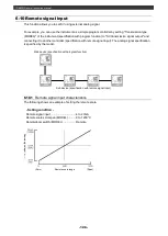
Page 128: ...utput and connecting it to another controller specification with remote signal input The analog signal specification is specified by the model Main device specification with program function Sub device specification with remote signal input 6 10 1 Remote signal input characteristics The following shows an example of setting the remote scale Setting condition Remote signal input 4 to 20mA Remote sc...

Page 129: ...calculation block diagram of cascade control Refer to the following figure as a guide to obtain the cascade input r ratio and cascade input b bias A shows a case of r 1 0 b a B shows a case of r 1 0 b 0 C shows a case of r S1 S0 b 0 Sensor Measurement input Primary controller output PID calculation Remote signal input Cascade calculation Output PV SV Zero Span Remote signal input Remote scale rang...

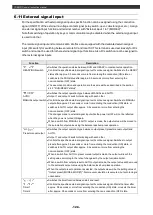
Page 130: ...Switches to MANUAL output after approx 0 5 seconds or more from entering the conduction ON state or switches to AUTO output after approx 0 5 seconds or more from entering the non conduction OFF state The changes made in external signal input while the power is OFF will not be reflected when the power is turned ON again When a switch from MANUAL to AUTO output is made the output value will be moved...

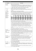
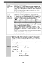
Page 131: ...ue operation by keys on the constant value operation screen set the external signal input to the BCD code other than the above execution No 1 to 8 Generally bring all the four external signal inputs into non conduction BCD code 0 to select the execution No for constant value operation on the constant value operation screen As an example it is possible to assign only the three external signal input...

Page 132: ... 3 PTN No 2 PTN No 1 PTN 4 ON OFF OFF OFF PTN 2 OFF ON ON OFF PTN 1 OFF ON OFF ON When the BCD code other than the above pattern No 1 to 4 is selected the pattern No will not be changed and the previous No will be retained Operation by keys or communication is unavailable while the pattern No selection is assigned to the external signal input To select the pattern No by keys on the program operati...

Page 133: ...port as standard The engineering port is located at the bottom of the case for DB630 and at the top of the case for DB650 670 Insert the dedicated USB engineering cable RZ EC3 sold separately to establish communication with a PC CHINO prepares the software for parameter setting It will help you set various parameters easily using the USB engineering cable and PC The communication specification of ...

Page 134: ...PC is also possible In addition there is a communication transmission digital transmission communication remote digital remote function This function enables a remote operation that produces no error by making the main device execute SV transmission and the sub device receive it as remote SV via communication The remote operation by remote signal input is called analog remote whereas the remote op...

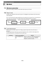
Page 135: ... transmitter 7 3 Lower limit burnout When the input line is disconnected the PV display jumps the lower limit and lower limit alarm is generated The input signal for lower limit burnout uses the only signal the same as that for standard upper limit burnout Note that there is no distinction from the under range PV display Alarm event operation Output Lower limit alarm turns ON Output 1 produces an ...

Page 136: ...nt for relay outputs such as ON OFF pulse ON OFF servo and event outputs We prepare the following contact protection elements Use one if necessary Model Specification Open close current Application CX CR1 0 01μF 120Ohm 0 2A or less Light loads CX CR2 0 5μF 47Ohm 0 2A or more Heavy loads Note that a leak current is generated as shown below when the contact protection elements are used depending on ...

Page 137: ... for approx three seconds Check the warning contents and try appropriate setting or operation Warning No Warning contents Program operation cannot be executed Check that the program pattern is set correctly Feedback tuning fails or the zero adjustment value of servo exceeds the span adjustment value Check the feedback input line if the connection is done properly for the OPEN and CLOSE sides Key l...

Page 138: ...eck items of the above PV display shows Indicates over range or upper limit burnout for the measuring range Check the sensor signal PV display shows Indicates under range for the measuring range Check the sensor signal Control is unstable Check that the wiring is done properly Check that the terminal screws are tightened firmly Check that there is no noise influence Check that the parameters PID o...

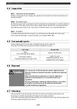
Page 139: ...e parts are subject to change or degradation over time Part name Expected life Relay For control and event outputs Approx 100 000 times Electrolytic capacitor Smoothing capacitor for power circuit Approx 5 years Ambient temperature 30 C operation time 12 hours day 8 6 Disposal Caution The components of this instrument contain a slight amount of hazardous chemical substance below the specified leve...

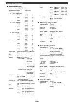
Page 140: ... 130dB or more 50 60Hz Series mode rejection ratio 50dB or more 50 60Hz Display specifications Display Segment type LCD LED backlight Control specifications Control interval Approx 0 1 seconds Output type ON OFF pulse output ON OFF servo output DB650 and DB670 only current output SSR drive pulse output voltage output ON OFF pulse output type Contact type 1a contact Pulse cycle Approx 1 to 180 seco...

Page 141: ...3 D Depth from panel surface is 65 DB670 96 W 96 H 73 D Depth from panel surface is 65 Weight DB630 Without option Approx 120g With option Approx 135g DB650 Without option Approx 150g With option Approx 230g DB670 Without option Approx 240g With option Approx 330g Terminal screw M3 0 Engineering port DB630 At the bottom of the case DB650 At the top of the case DB670 At the top of the case Referenc...

Page 142: ...rent measuring range 5 0 to 50 0A AC Measurement category None Input signal 5 0 50 0A 50 60Hz Accuracy 5 0 of FS 1digit Transmission signal output option Output point 1 point Output signal 4 to 20mA DC load resistance 400Ohm or less 0 to 1V DC load resistance 50kOhm or more 0 to 10V DC load resistance 50kOhm or more Accuracy 0 3 of FS Output updating interval Approx 0 1 seconds Insulation Non isol...

Page 143: ...800 C 0 8 FS 1digit Au Pt 0 0 to 1000 0 0 1 of FS 1digit Resistance thermometer Pt100Ohm1 200 0 to 850 0 0 1 of FS 1digit Pt100Ohm2 200 0 to 200 0 JPt100Ohm1 200 0 to 649 0 JPt100Ohm2 200 0 to 200 0 Pt50Ohm 200 0 to 649 0 DC voltage 20mV 20 00 to 20 00 0 1 of FS 1digit 100mV 100 0 to 100 0 5V 5 000 to 5 000 10V 10 000 to 10 000 Accuracy indicates the performance under reference operating condition...

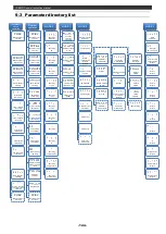
Page 144: ...attern repeat to time Operation screen time display Step elapsed time Step remaining time Pattern clear No pattern clear Initialize pattern No 1 to Initialize pattern No 4 Initialize all patterns Screen Item Setting range Default Pattern copy No pattern copy Copy pattern No 1 to No 2 to Copy pattern No 4 to No 3 Number of steps to No step to 1 to 12 steps Program operation PV start SV start PV sta...

Page 145: ... Communication protocol MODBUS RTU MODBUS ASCII Private Communication function Host communication Digital transmission Digital remote input Instrument No to Communication transmission rate 4800bps 9600bps 19200bps 38400bps Communication character 7 bit even parity stop bit 1 7 bit even parity stop bit 2 7 bit odd parity stop bit 1 7 bit odd parity stop bit 2 8 bit no parity stop bit 1 8 bit no par...

Page 146: ...on parameter Executing SV Executing step time Executing event 1 Executing event 2 Executing event 3 Executing event 4 Executing P Executing I Executing D Executing output limiter L Executing output limiter H Executing guaranty soak MODE 1 Constant operation parameter SV rate of change for rise SV rate of change for fall SV rate of change unit Constant value operation PV start Alarm action in READY...

Page 147: ...ration Output 2 output preset Split Dir Split Rev Output 2 pulse cycle Output 2 output limiter L Output 2 output limiter H Output 2 variation limiter L Output 2 variation limiter H Output 2 preset manual MODE a Communication parameter Communication protocol Communication function Instrument No Communication transmission rate Communication character Digital transmission type Digital transmission cy...

Page 148: ...on for program operation 76 F FB dead band 91 FB tuning 48 FB zero span 91 G Guaranty soak 68 I Instrument No 100 Input type 87 K Key lock 109 L Linear scale 88 Local 104 M Measuring range 88 Measuring range 111 N Number of steps 75 O Output at the end of program operation 76 Output dead band 92 Output preset 92 Output variation 93 Output limiter 68 Output 2 gap 98 P Pattern clear 74 Pattern link ...

Page 149: ......

Page 150: ...CHINO CORPORATION 32 8 KUMANO CHO ITABASHI KU TOKYO 173 8632 Telephone 81 3 3956 2171 Facsimile 81 3 3956 0915 Printed in Japan ...

Reviews: