Chauvin Arnoux C.A 6160 User Manual Download Page 44

44

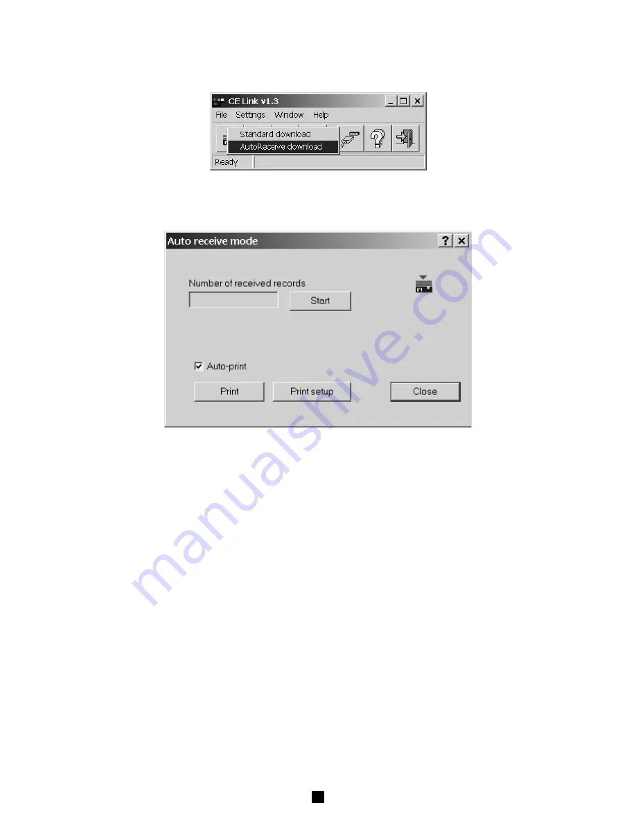
For auto download from instrument (instrument must be in the Autotest mode) choose AutoReceive download
option. In this mode PC waits to receive record from the instrument. Instrument sends record to the PC at the end of
each sequence procedure. After downloading the sequence will be executed again. For details of sequence creating
see  chapter 7.6  Sequence editor (in program definition window AutoSend option has to be enabled)

Fig. 67. Auto receive download  mode

After the file name for storing downloaded data is defined the ‘Auto receive mode’ window will appear.

Fig. 68. Auto receive download  mode

Before starting of the autotest you should press Start button in the Auto receive mode window.
There is a counter for the number of received records since Start pressed.

Auto receive mode enables two different ways for printing received results:

- Auto print

( automatically prints the results after each reception)

- Manual print

(print results after Print button in the Auto receive mode

is pressed)

At the end of auto download you should press Stop button in the Auto receive mode window.

7.4. OPEN DATA FILE

To open one of downloaded data files press “Open data file” button in basic screen. Window for file selection will be displayed.

Summary of Contents for C.A 6160

Page 1: ...1 APPLIANCE MULTITESTER C A 6160 E N G L I S H User s Manual...

Page 2: ...tion resistance p 18 4 6 Discharge time external input MAINSTEST p 20 4 7 Discharge time internal p 21 4 8 Leakage current p 22 4 8 1 Leakagecurrent p 22 4 8 2 Touch Leakage current p 23 4 8 3 Substit...

Page 3: ...s familiar with hazardous voltage operations can handle APPLIANCE MULTITESTER Meaning of signs on front panel Insulation section Dangerous voltage may be present measurements shall be carried out only...

Page 4: ...antee period will not result in this guarantee being extended 1 3 LIST OF MEASUREMENTS CARRIED OUT BY THE INSTRUMENT Withstanding programmed voltage time sequence test Withstanding voltage test High v...

Page 5: ...ng lamp 13 START STOP push button 14 General keys F1 to F4 function of each key is shown on display 15 SET key press when the instrument is switched ON Set date time Set serial port baud rate Set barc...

Page 6: ...6 5 7 0 7 5 8 0 8 5 9 0 9 5 10 20 30 40 50 60 70 80 90 100 150 200 250 300 350 400 450 500 mA For test voltages greater than 1000 V maximum current limit depends on max high voltage power characteris...

Page 7: ...ains 230 V original test leads 200 mA at R 8 Umains 230 V original test leads 10 A at R 0 5 Umains 230 V original test leads 25 A at R 0 2 Umains 230 V original test leads Current shape sinusoidal Thr...

Page 8: ...to original test cable 10 A Timer adjustable 1 59 s resolution 1 s Connection system 4 wire safety connectors electrically separated 3 5 INSULATION RESISTANCE Nominal voltage 250 V 500 V 1000 V Insul...

Page 9: ...RRENT Substitute leakage current readout Range mA Resolution mA Accuracy 0 00 20 0 0 01 5 of reading 3digit Settable limits 0 1 20 0 mA in step of 0 1 mA Short circuit current 30 mA Open circuit volta...

Page 10: ...play LCD dot matrix 160 x 116 dots with cont backlight RS232 interface 1 start bit 8 data bits 1 stop bit RS232 baud rate adjustable 9600 19200 38400 Baud Memories 1638 memory locations Remote control...

Page 11: ...nd connected accessories as the Withstanding test sockets and leads are under the hazardous voltage Never touch exposed probe tip connected equipment under test or any other energized part during the...

Page 12: ...ey to set burn m ode Fig 4 Main menu in HV function STEP 2 Select test parameters as follows Test voltage Use UN key to select appropriate test voltage that can be set using keys from 100 V to 1000 V...

Page 13: ...tion is displayed Use and keys to select appropriate test time value To deactivate the timer press Toff key or Ton key to activate it See the following figure A fter presing key test tim e is not disp...

Page 14: ...limit HV generator trips automatically after reaching that value Preset limit value is displayed as a result in this instance STEP 7 Save displayed result for documentation purpose see instruction in...

Page 15: ...o t2 and value T3 represent time from t2 to t3 fig 12 Menu for selection and changing values is displayed see the following figure Fig 12 Timer T1 is selected change value by using keys To select ramp...

Page 16: ...voltage drop m ode Threshold resistance Test voltage Test current Set tim er value Tim er A U TO key to set tim er value or to set m ode R esistance m ain result R m ax key to set threshold resistance...

Page 17: ...ntinuity test terminals The flow of a small current across the tested item when the test terminals are connected will activate the measurement By turning the ROTARY SWITCH or switching off the instrum...

Page 18: ...nnect test probes to the instrument and to equipment under test as shown in the following figure U I test test U 0V 10V scaled to 10A 12V 50 60 H z 10A for R 0 500m Fig 19 Connection of test leads STE...

Page 19: ...tion resistance threshold selection menu Use and keys to select appropriate threshold value If the displayed result is lower than the set threshold limit value it will be accompanied by an error sound...

Page 20: ...ltage of the currently connected mains supply system The instrument is constructed to measure external discharge time in three different mains supply systems 115 V 230 V and 400 V The voltage is calcu...

Page 21: ...gged in etc STEP 6 Pull out double connection element and wait for the result to be displayed If the disconnection voltage is high enough to carry out a measurement see fig 25 Start message is display...

Page 22: ...riate less than min working voltage or not connected check input circuit mains voltage STEP 6 Pull out power supply connector and wait for the result to be displayed If the disconnection voltage is hi...

Page 23: ...o select appropriate threshold value Press Exit key to exit menu Timer value See instructions on how to set the value in paragraph 4 1 STEP 2 Timer ON OFF See instructions in paragraph 4 1 STEP 2 STEP...

Page 24: ...1 STEP 2 Timer ON OFF See instructions in paragraph 4 1 STEP 2 STEP 3 Connect tested item into test socket on the instrument as shown in figure below Fig 37 Connection of tested object STEP 4 Press ST...

Page 25: ...nstructions in paragraph 4 1 STEP 2 STEP 3 Connect tested item into test socket on the instrument as shown in figure below Fig 40 Connection of tested object STEP 4 Press START STOP key to start the m...

Page 26: ...easier more flexible or even automatic It gives an assurance that the complete measurement procedure is carried out Any previously designed sequence by CE Link software up to 10 sequences each compos...

Page 27: ...he APPLIANCE MULTITESTER How to carry out the measurement STEP 1 Install CE Link PC software on your PC STEP 2 Using Sequence editor create the desired sequence Max number of steps for each sequence i...

Page 28: ...STEP 11 DISCHARGE Internal U 60 V t 5 s STEP 12 MESSAGE LEAK L to PE FUNCT notice to prepare device for DISCH test and after PAUSE for FUNCT Test STEP 13 LEAKAGE CURR Ilim 1 mA time 5 s STEP 14 PAUSE...

Page 29: ...29...

Page 30: ...tage on term ISO External AC or DC voltage connected to ISO terminals is higher than 30 V DISCHARGING TIME FUNCTION Ready displayed for approx 1 s after pressing START LowVoltage displayed if the volt...

Page 31: ...Press MEM key in order to reach memory menu for saving results see fig below M EM key to select m emory operation m enu D evice num ber N um ber of m em orized results under displayed device num ber B...

Page 32: ...r Exit to cancel clearing procedure STEP 3 Press MEM key to recall saved results under chosen device Fig 51 Recalled result under device 001 STEP 4 Select result you are looking for by using and keys...

Page 33: ...d keep it pressed while switching on the instrument STEP 3 System configuration menu is displayed see figure below Fig 54 Basic system configuration heading STEP 4 Use and keys to select one of displa...

Page 34: ...d losing important data CLEAR all PROGRAMS Press Enter to confirm or Exit to cancel clearing of memory NOTE Before clearing download all memorized results to PC to avoid losing important data LOAD DEF...

Page 35: ...o r p o ssib le values Initial value IN test current 100 m A 200 m A 10 A 25 A 10 A R m ax m ax allow ed resistance 10 990 m by steps of 10 m 1000 2000 m by steps of 100 m or no lim it 100 m C ontinu...

Page 36: ...TE The selected contrast may change due to a change in temperature of the display instrument heat or changed ambient temperature 5 7 USE OF REMOTE CONTROL PEDAL The pedal is intended to start and stop...

Page 37: ...e the result by pressing SAVE pedal twice STEP 5 Proceed with the measurements Technical specifications of the pedal Cable length 10 m Commands START STOP SAVE Casing metal Weight 2 kg Size W H D 300...

Page 38: ...Pin 4 Next test digital output Pin 5 Door in digital input Pin 6 Gnd 5 10 1 DOOR INPUT If the DOOR IN input is enabled see chapter 5 5 System configuration tests in PROG HV and HV position will not b...

Page 39: ...In this case the total pause between two sequent measurements is predefined time pause Time of Pause command 3 Message it has to be inserted as a Message command in the SQC program The instrument wait...

Page 40: ...nstrument 6 4 REPLACING THE FUSES BY PROPERLY TRAINED SERVICE PERSONNEL ONLY In the case of instrument malfunction send the instrument to an appropriate service center for all four fuses to be checked...

Page 41: ...you select After installation is done you are able to run CE Link exe from Start menu WARNING This program is protected by copyright law and international treaties Unauthorized reproduction or distri...

Page 42: ...EFINE HEADER FOR PRINTED DOCUMENTS Shortcut key Alt F H Exit Exits CE Link Shortcut key Alt F E Sequence editor Tool for programing AUTOTEST sequences Shortcut key Alt F S Table 1 Fast access buttons...

Page 43: ...on by pressing RS232 key instrument will go in communication mode Choose Download Standard download data option in main CE Link window Fig 65 Standard download mode After message Downloading in progre...

Page 44: ...is defined the Auto receive mode window will appear Fig 68 Auto receive download mode Before starting of the autotest you should press Start button in the Auto receive mode window There is a counter f...

Page 45: ...file window In the table all failed measurements will be marked by red color By using search button see table 2 the user can easily jump from one to another failed measurement For table editing for e...

Page 46: ...Shortcut key Alt E Mark Unmark row Marks or unmarks important row Shortcut key Alt E D Print Prints open data fille Shortcut key Alt F P ReArrange numbers Rearranges from top to bottom device and memo...

Page 47: ...To create header select Define header in File menu 4 Choose Print form Print menu Header options define header height include bitmap file user logo in our example windows clouds bmp underline header w...

Page 48: ...2 PRINT preview 7 5 2 PRINT SEPARATELY Print separately function prints each measured device results to its own document It is intended to print separate reports for each tested object production line...

Page 49: ...header the instrument has to be connected to PC User can change User string max 48 characters send system time time and date set on the PC It is possible to change User string only in this way Instru...

Page 50: ...und signals Max number depends on combination of included function in current example Fig 74 Sequence editor window Two main parts of Sequence editor are Command table and Program table Command table...

Page 51: ...51 Voltage drop Parameter window Continuity Current Parameter window High Voltage Parameter window Programed High Voltage Parameter window Insulation Parameter window Sound Parameter window...

Page 52: ...s 5 s between each test of the sequent saving of measurement results increment device number for successive sequence results auto send each sequence results to PC suitable for automate of production l...

Page 53: ...row Shortcut key Alt S P Get command Copies selected command from command table to program table Shortcut key Alt F O Insert empty row Inserts an empty row at selected row for a new command Shortcut...

Page 54: ...ntrol probe P01 1019 16 Warning lamps green red P01 1019 17 2 dielectric test guns with cable 6m P01 1019 18 1 adapter DB9M DB9F P01 1019 41 SPARE PARTS 1 bag for accessories P01 2980 61 2 dielectric...

Page 55: ...lerstrasse 535 8810 HORGEN T l 01 727 75 55 Fax 01 727 75 56 UK Waldeck House Waldeck Road MAIDENHEAD SL6 8BR T l 01628 788 888 Fax 01628 628 099 Liban P O BOX 60 154 1241 2020 Jal el dib BEYROUT T l...

Reviews: