Ceragon FA4800 User Manual Download Page 268

BRS Link Configuration

Chapter 23

FA4800 User Manual

Release  1.9.30

23-3

BRS Link Configuration

The BRS link is reconfigured during the Link Installation or the Link Configu-
ration wizards, or from the Air Interface screen.

¾

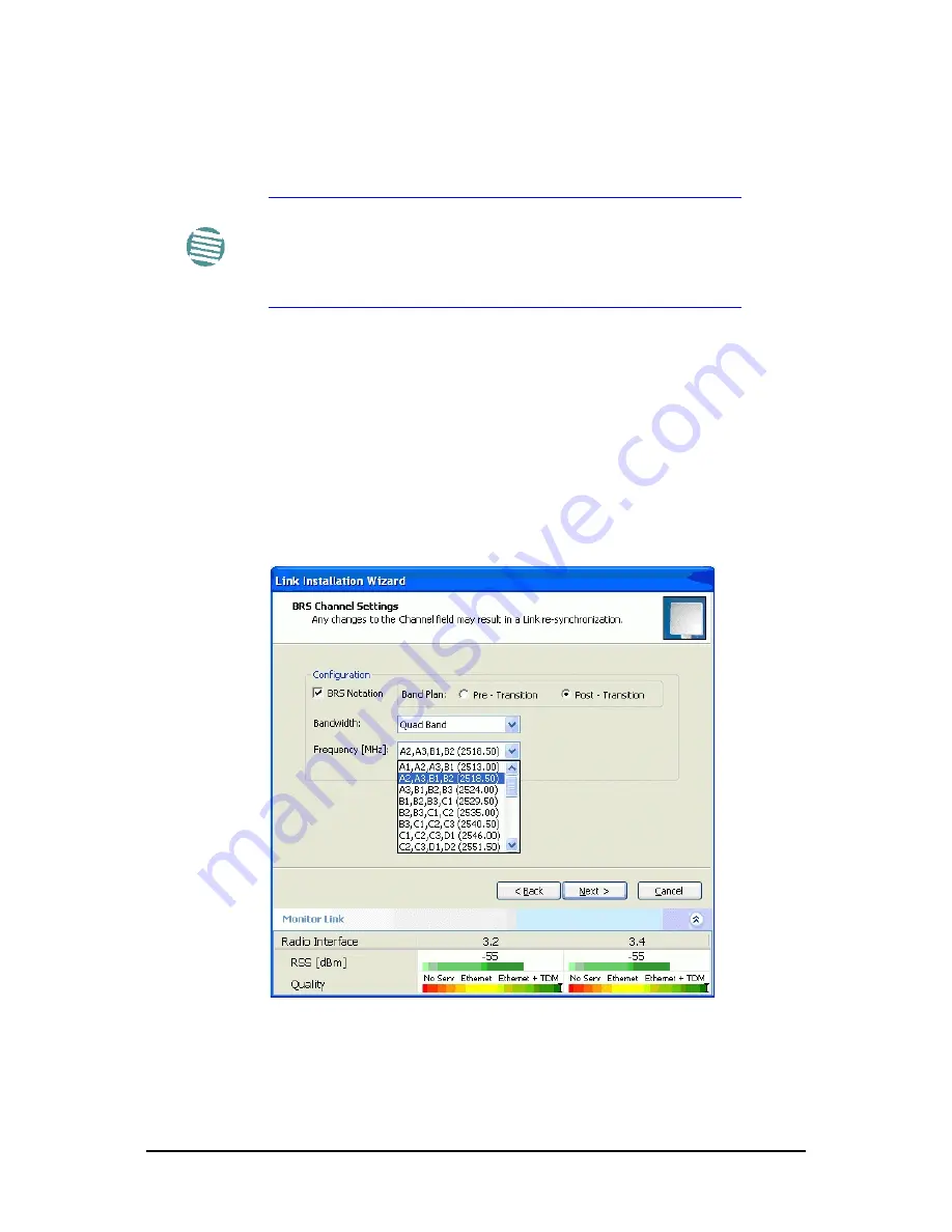
To Configure BRS Channel Settings:

1. Set the Band Plan.

2. Select the Bandwidth required, 

• Single  Band
• Double  Band
• Quad  Band

3. Select the Frequency from the pull-down menu.

4. Click Next. The system is re-synchronized to the changes.

Figure 23-4: BRS Channel Settings Post-Transition

Note

Both sites in a BRS Link must be configured identically.

Any changes to the frequency settings cause the link to re-

synchronize. A short loss of service will occur during re-

synchronization.

Summary of Contents for FA4800

Page 1: ...FA4800 Broadband Wireless Transmission System USER MANUAL RELEASES 1 9 30...

Page 2: ...r respective holders TradeMarks CeraMap ConfigAir PolyView EncryptAir CeraMon EtherAir and MicroWave Fiber are trademarks of Ceragon Networks Ltd Other names mentioned in this publication are owned by...

Page 3: ...ro ceragon com APAC Singapore Ceragon Networks APAC Pte Ltd 100 Beach Road 27 01 03 Shaw Towers Singapore 189702 Tel 65 6572 4170 Fax 65 6572 4199 Email infoAPAC ceragon com APAC India Ceragon Network...

Page 4: ...iver is connected Consult the dealer or an experienced radio TV technician for help Changes or modifications to this equipment not expressly approved by the party responsible for compliance could void...

Page 5: ...trical Safety Code ANSI IEEE C2 must be considered during installation NOTES 1 A Primary Protector is not required to protect the exposed wiring as long as the exposed wiring length is limited to less...

Page 6: ...tionality with FA4800 Chapter 15 Software Upgrade Chapter 16 FCC IC DFS Installation Procedure Part 4 Field Installation Topics Chapter 17 Pole and Wall Installation Chapter 18 Lightning Protection an...

Page 7: ...s 1 12 Flat Panel Antennas 1 13 Parabolic Dish Antennas 1 13 Grid Antennas 1 14 FibeAir2000 Manager 1 14 Accessories 1 15 Documentation supplied with FA4800 1 15 How to Use this Manual 1 16 A Little T...

Page 8: ...IDU 3 13 Connecting the ODU to the IDU 3 13 Installing a Link using PoE Devices 3 13 Connecting User Equipment 3 14 Connecting and Aligning ODUs Antennas 3 14 Chapter 4 Getting Started with the FibeAi...

Page 9: ...guration Configuring the Site 8 1 Editing the Configuration Parameters by Site 8 1 Functions on the left of the dialog box 8 2 Functions at the top of the dialog box 8 2 Viewing System Details 8 3 Vie...

Page 10: ...e Events Log 9 14 FibeAir2000 Manager Traps 9 16 Setting the Events Preferences 9 17 Saving the Events Log 9 17 Active Alarms 9 18 Viewing Recent Events 9 18 Reverting Alert Messages 9 19 Other Advanc...

Page 11: ...gy 13 1 Ceragon Ethernet Ring 13 2 Ethernet Ring Topologies Supported by Ceragon 13 4 Protection Switching 13 5 Hardware Considerations 13 5 Special Case 1 1 Ethernet Redundancy 13 6 Using FibeAir2000...

Page 12: ...20 1 Changing Band for DFS 20 5 Special Products or Features Entering a License Key 20 5 Chapter 21 Link Budget Calculator Overview 21 1 User Input 21 1 Link Budget Calculator Internal Data 21 1 Calc...

Page 13: ...ix D MIB Reference Introduction D 1 About the MIB D 1 Terminology D 1 Interface API D 1 Control Method D 1 Community String D 2 Private MIB Structure D 2 MIB Parameters D 3 Supported Variables from th...

Page 14: ...FA4800 User Manual Release 1 9 30 xiii Montage d une antenne externe G 6 Contenu du kit de montage d une antenne externe G 6 Appendix H Old Style IDU E Details Index...

Page 15: ...EXTERNAL ANTENNAS GRID ANTENNA 1 14 FIGURE 1 24 FIBEAIR2000 MANAGER WINDOW 1 15 FIGURE 1 25 MENU NAVIGATION IN THE FIBEAIR2000 MANAGER 1 19 FIGURE 1 26 SITE CONFIGURATION WINDOW WITH OPEN MANAGEMENT...

Page 16: ...FIGURE 5 21 INSTALLATION WIZARD EXIT SUMMARY 5 18 FIGURE 5 22 MAIN WINDOW OF THE MANAGER AFTER INSTALLATION WITH LOADED TRUNKS5 19 FIGURE 6 1 MAIN WINDOW WIRELESS LINK IS ACTIVE 6 2 FIGURE 7 1 LINK C...

Page 17: ...NTS AT SITE A 9 19 FIGURE 9 20 ADVANCED PREFERENCES 9 19 FIGURE 10 1 INTERFERENCE CAUSED BY COLLOCATED UNITS 10 2 FIGURE 10 2 COLLOCATED UNITS USING HUB SITE SYNCHRONIZATION 1 10 2 FIGURE 10 3 COLLOCA...

Page 18: ...SINGLE SITE ADDED FOR UPGRADE 15 3 FIGURE 15 5 SOFTWARE UPGRADE SITE OPTIONS 15 4 FIGURE 15 6 SOFTWARE UPGRADE IN PROGRESS NOTE THE STOP BUTTON 15 4 FIGURE 15 7 SOFTWARE UPGRADE COMPLETED SUCCESSFULLY...

Page 19: ...21 11 CLIMACTIC C FACTOR DESCRIPTION 21 12 FIGURE 21 12 WORLD MAP SHOWING C FACTOR CONTOURS 21 12 FIGURE 21 13 SERVICES SELECTOR 21 13 FIGURE 22 1 FA4800 LINK SETUP 22 1 FIGURE 23 1 INACTIVE LINK STAT...

Page 20: ...AP MESSAGES 9 16 TABLE 9 6 ACTIVE ALARMS COMMAND BUTTONS 9 18 TABLE 9 7 LED FAULT INDICATORS 9 20 TABLE 9 8 SYSTEM TROUBLESHOOTING 9 21 TABLE 10 1 ODU HSS UNIT CONNECTION PINOUT 10 7 TABLE 10 2 RADIO...

Page 21: ...U E AL OUTPUT ALARMS DESCRIPTION E 2 TABLE E 4 IDU E AL INPUT ALARMS DESCRIPTION E 2 TABLE E 5 POE 8 OUTPUT ALARMS DESCRIPTION E 3 TABLE F 1 SAFETY DISTANCES FOR FA4800 FCC AND IC PRODUCTS F 1 TABLE F...

Page 22: ...FA4800 Broadband Wireless Transmission System USER MANUAL RELEASE 1 9 30 Part 1 Basic Installation...

Page 23: ...0 Km 50 miles the FA4800 products offer an unmatched combination of robustness and reliability at an affordable price About Release 1 9 30 Release 1 9 30 of FA4800 brings together incremental changes...

Page 24: ...k Connectivity Cellular Backhaul FA4800 products enable cellular carriers to expand their networks in both urban and rural areas quickly and cost effectively FA4800 systems are ideally suited for a br...

Page 25: ...llow organizations and sys tem integrators to deploy video cameras virtually anywhere while eliminat ing the costs and installation hassles of wire based systems Reliable robust and affordable the FA4...

Page 26: ...p to 80 Km 50 miles FA4800 provides very high capacity as well as a unique combination of TDM and IP services over the same link Figure 1 5 Private Network Figure 1 6 Multi Point to Point Enterprise C...

Page 27: ...00 and FibeAir 2000 units thus virtually reducing mutual inter ference commonly experienced with collocated TDD radios HSS Interoperability between FibeAir 2000 and FA4800 Site Synchronization is supp...

Page 28: ...and performance monitoring capabilities Multiple FA4800 links can be managed by Ceragon Network Manage ment System RNMS SFP support in the IDU C Standard SFP modules are used enabling any type of Ethe...

Page 29: ...e 1 8 below depending on the type of antenna ODU with integrated 1ft flat panel antenna Integrated Antenna ODU This unit contains both the ODU and antenna as a single unit housed in a weatherproof cas...

Page 30: ...ut 2Mbps 2 5 Mbps 18Mbps 18Mbps Max Range 20Km 20Km 80Km 80Km SupportedIDU devices PoE PoE PoE and IDU PoE and IDU Services Ethernet Ethernet Ethernet and TDM Ethernet and TDM HSS Yes Yes No Yes Tx Po...

Page 31: ...ement Figure 1 9 AIND All Indoor unit connected to antenna The Indoor Unit IDU The IDU has the service ports and provides aggregation of these services towards the ODU that transports them over the ai...

Page 32: ...rnal alarms interface It looks the same as the IDU E above without the HSS LED The IDU R is an indoor unit used for automatic backup of leased lines The IDU R monitors the status of leased lines and i...

Page 33: ...only Figure 1 14 IDU C Ethernet only front panel Figure 1 15 IDU C 4 E1 T1 ports front panel You can use an IDU C with 4 8 or 16 ports FA4800 will recognize ports 1 4 only Power Over Ethernet PoE Dev...

Page 34: ...t This unit can only be used with FA4800 radios Figure 1 18 O PoE device Input is mains AC power PoE 8 The PoE 8 is a 19 inch 1U metal unit providing 8 Ethernet ports enabling connection to collocated...

Page 35: ...0 ODU with integrated antenna side and front views Various external antennas are available for the FA4800 operating frequen cies Flat Panel Antennas The Flat Panel antenna shown in Figure 1 21 is avai...

Page 36: ...installation and configura tion of the link between the ODU units The intuitive easy to use FibeAir2000 Manager has a graphical Microsoft Windows interface and can be run locally and remotely The Fib...

Page 37: ...ing Protection Units Cables to connect the various system elements Grounding cables Documentation supplied with FA4800 The technical documentation supplied with a FA4800 is located on the product CD I...

Page 38: ...a matter of convenience A link then consists of two sites In Broadband Wireless terminology the local and remote sites are some times referred to as near and far HQ and remote and so on Table 1 3 User...

Page 39: ...he air site Which is which is always determined by the loca tion of the managing computer FA4800 supports three connection methods for the managing computer Local a direct peer to peer connection betw...

Page 40: ...sing Boldface for the menu labels and vertical bars to separate them Note The purpose of a Note is to Draw your attention to something that may not be obvious or coun ter intuitive Emphasize a special...

Page 41: ...ferred to as a window the main window or the Manager window depending on context The top line of icons is the tool bar and provides part of the menu bar functionality with a mouse click At the bottom...

Page 42: ...point Tahoma typeface for main text Tables for most part use 7 or 8 point fonts Here are a few pointers for hard copy printing The text and table typefaces used are large enough to print the manual at...

Page 43: ...e determined on site 3 Radio Frequency RF survey It is recommended that the installation area be scanned with a spectrum analyzer to identify RF interference so as to determine a clear channel for rad...

Page 44: ...tes on a topographic map of the area 2 Measure the distance between the sites check that it is within the speci fied range of the equipment 3 On the urban map check for developed areas situated betwee...

Page 45: ...above any obstructions con sidering the Fresnel zone see 21 4 If you need to install the ODU on a tower make sure that the tower is far away from overhead electric power lines 5 Determine a location...

Page 46: ...er functions You should perform the RF survey at both proposed link sites The survey should be carried out during a busy time of day to best judge the worst case radio interference Allow 2 4 hours dur...

Page 47: ...ation wizard In the Channel Settings window use the quality bar at the bottom to help you choose a better channel clearer of interference If you are using FA4800 radios install the collocated links wi...

Page 48: ...ertently in front of the antenna Grounding All Ceragon products should be grounded during operation In addition The ODU should be earthed by a wire with diameter of at least 12AWG The FA4800 ODU must...

Page 49: ...ecting the ground More detailed guidelines are supplied in Chapter 18 Protection against Lightning The use of lightning protection is dependent on regulatory and end user requirements All of Ceragon o...

Page 50: ...An ODU mounting kit see Figure 3 1 below A CD containing the FibeAir2000 Manager Quick Start Guide User Manual the document you are reading Link Budget Calculator Label showing the MAC address and th...

Page 51: ...verter IDU E wall mounting drilling template Self adhesive label showing the IDU LED operation Figure 3 4 IDU E R front view IDU C Package Contents The IDU c package contains IDU C see Figure 3 5 belo...

Page 52: ...ugs PoE 8 Package Containing Figure 3 8 PoE 8 Unit PoE 8 110 240 VAC with IEC 60320 socket cable 3 prong terminal block connector green 19 mounting kit External Antenna Package Contents Antenna RF cab...

Page 53: ...class CAT 5e 4 twisted pairs 24AWG For PoE based links A crossed Ethernet LAN cable O PoE 10AWG grounding cable if applicable BDU grounding cable 18AWG if applicable Hardware Installation Sequence The...

Page 54: ...IP address This may be done prior to deployment in the field or on site using a Laptop computer The process is quite straight forward and described in Chapter 19 Mounting the ODU The ODU can be mounte...

Page 55: ...Refer to Chapter 17 for detailed antenna mounting instructions 2 Follow the mounting instructions supplied with the antenna Mounting the Lightning Protection Devices The use of lightning protection i...

Page 56: ...n Installing IDU E and R units IDU E Installation The IDU E can be wall mounted placed on a desktop or take up one half of a 1U rack slot The unit should be grounded cabled to the ODU and con nected t...

Page 57: ...ow Figure 3 12 IDU C front panel In Figure 3 13 we display a perspective view of the IDU C Figure 3 13 IDU C A perspective view Further description of the keyed items in Figure 3 12 is shown in Table...

Page 58: ...pin Power Connector I Grounding Lug Use the lug supplied J Rack mounting holes K Detachable Rack mounting brackets L 0 4 8 or 16 E1 T1 Ports See Table B 5 M Standby Port Hot Standby ready HSB cable s...

Page 59: ...ary Secondary Primary Secondary Off Active Not active Not active Active HSM not activated Table 3 3 IDU C and New Style IDU E Front Panel LEDs for HSS Color Function Green This ODU is HSS master gener...

Page 60: ...power to the ODU The maximum length of the ODU IDU cable is 100m 328ft in accordance with 10 100BaseT standards The ODU IDU cable is supplied pre assembled with RJ 45 connectors at the length specifi...

Page 61: ...other compatible device to the SFP plug in module Refer to Appendix B for connector pinouts To connect user equipment to a PoE device Connect a user switch router or any other compatible device to th...

Page 62: ...from site B can be detected 5 Slowly turning the site A ODU back towards the position of Site B listen to the tone until the best signal is reached See the following figure for audible signal variatio...

Page 63: ...tems are Hard disk 1 GB free space Network 10 100BaseT NIC Graphics 1024x768 screen resolution with 16 bit color Microsoft Explorer version 5 01 or later Installing the Software Any PC running the Fib...

Page 64: ...000 Manager 1 Connect the managing computer to one of the two LAN ports as shown in Figure 4 1 below Figure 4 1 LAN ports on the front panel of the IDU C If you are not using a direct connection as ab...

Page 65: ...succeed seek assistance from Ceragon Customer Support 3 Dismiss the command line session 4 Double click the FibeAir2000 Manager icon on the desktop or click Start Programs FibeAir2000 Manager FibeAir...

Page 66: ...ndowAt the User Type field click the list button Figure 4 4 Log on window exposing the user types There are three user types An Observer has read only access to the link An Observer can monitor the li...

Page 67: ...rator admin Installation configuration Read Write netman Installer wireless Operator plus set band Read Write netman Warning If you log on using Local Connection but your physical connection is not lo...

Page 68: ...h read only permission then you may only log on as Observer The FibeAir2000 Manager main window is displayed see Figure 4 9 Log on Errors and Cautions Unsupported Device Attempting to connect to an un...

Page 69: ...you will be first offered the following caution Figure 4 8 Logging on to an over the air site Continuing without an IP Address The FibeAir2000 Manager provides limited offline functionality when there...

Page 70: ...Calculator opened in default browser 21 Get Diagnostics Information Obtain system information page 9 1 About FibeAir2000 Manager FibeAir2000 Manager build information Note A valid log on password must...

Page 71: ...4 FA4800 User Manual Release 1 9 30 4 9 Figure 4 9 Opening FibeAir2000 Manager window prior to installation IDU C and new style IDU E Figure 4 10 Opening FibeAir2000 Manager window prior to installat...

Page 72: ...processes The Wizards are visu ally quite similar and will be described in detail below 3 Site Configuration described in 8 Site specific configuration for each side of the link is available at any t...

Page 73: ...5 780GHz ODU IP Address 10 0 0 120 192 168 2 101 and 102 Subnet Mask 255 0 0 0 255 255 255 0 Trap destination 0 0 0 0 0 0 0 0 FibeAir2000 Manager log on passwords Observer admin Operator admin Install...

Page 74: ...e For the purpose of explanation we will set up a laboratory link with the fol lowing characteristics Channel selection Automatic Services Ethernet 3xE1 on ports 1 2 3 using IDU As The Installation wi...

Page 75: ...Installation Wizard 1 Wizard welcome 2 System parameters Link ID Site details 3 Channel settings ACS Configuration 4 HSS Settings 5 Services Types Ethernet TDM Adaptive or fixed Jitter Buffer MHS Ethe...

Page 76: ...nas are properly aligned If this box is grayed out you should align the antennas as set out in 3 on page 3 17 The Installation Wizard opens Figure 5 1 Link Installation Wizard The bottom data area rep...

Page 77: ...ntification The default name is Link You should change it 3 Enter names for Site 1 and Site 2 The default names are both Location You should change them Throughout this manual we use A for Site 1 and...

Page 78: ...ed The Channel Setting dialog box appears Proceed to Channel Settings below Changing the Link Password The default password is wireless bridge Optionally you can change the link password as explained...

Page 79: ...Link Password and click OK to finish You are returned to the window in Figure 5 4 above Continue with the next step 3 Enter a new password 4 Retype the new password in the Confirm field 5 Click OK 6...

Page 80: ...vailable channel in a list of monitored channels nominated in the Channel settings window of Figure 5 6 below A channel switch takes place sufficiently fast as to ensure no loss of service Figure 5 6...

Page 81: ...apter 5 FA4800 User Manual Release 1 9 30 5 8 Figure 5 7 Channel Settings Showing available installation rates 2 Choose the required Channel Bandwidth Figure 5 8 Channel Settings Showing available Cha...

Page 82: ...ual ity bar provides an indication of the link quality from No serv ice red to Ethernet TDM green as shown in the bottom of Figure 5 7 above 5 Click Next Step 4 Hub Site Synchronization Settings Figur...

Page 83: ...30 5 10 Figure 5 10 Services and Rates TDM Services selection To select services 1 Click the Configure button The TDM services dialog is displayed 2 Using the TDM Type radio buttons choose E1 or T1 Y...

Page 84: ...he Select Maximum button to choose all available ports Figure 5 12 TDM Service port selection seven services selected 4 Click OK You are returned to the Services and rates dialog of Figure 5 14 It is...

Page 85: ...FA4800 User Manual Release 1 9 30 5 12 Figure 5 13 Services and Rates Services chosen Modulation Rate Selection You may choose a specific modulation rate or use Adaptive Figure 5 14 Services and Rates...

Page 86: ...eturned to the Services and rates dialog of Figure 5 14 Setting Monitored Hot Standby Mode If you are not using Hot Standby Mode you may skip this section To install and use the Hot Standby feature se...

Page 87: ...by increasing system resistance to interference the larger the jitter buffer the longer the interference period that the system will overcome without TDM errors You can also decrease the jitter buffer...

Page 88: ...17 TDM Jitter Buffer Configuration ETBE evaluation bar 2 After setting the jitter buffer size if grayed out the Evaluate button is enabled while both Back and Next are disabled as shown in the next f...

Page 89: ...dialog is displayed Figure 5 19 TDM Parameters Configuration 1 To configure TDM clock parameters 1 For any individual port click it For the same parameters for all ports click the Select Maximum tag N...

Page 90: ...ters Transparent Transparent The clock at Site A regenerates the clock from Site B and vice versa Loop time Recover The Site A port receive clock is used as the transmit clock for that port on both si...

Page 91: ...at the Site A port Recover Internal The Site B port uses its internal oscillator to generate its transmit clock while the Site A port regenerates the clock received at the Site B port 4 Click Finish...

Page 92: ...ccording to expected results as determined by the Link Budget Calculator Caution Installation mode as described above may be re entered using Site A or Site B and Installation Mode in the Site Configu...

Page 93: ...FibeAir2000 Manager application is largely generic to all Ceragon Radio Products Functionality differences are minimal according to radio series FA4800 and FibeAir 2000 capabilities The Main Window o...

Page 94: ...FibeAir2000 Manager toolbar contains the fol lowing buttons In Installation mode Link Configuration is grayed out and Link Installation is open The button functions are set out in Table 6 1 Table 6 1...

Page 95: ...r2000 Manager Exit Exits FibeAir2000 Manager Help Opens Help on the use of contextual online help Table 6 2 FibeAir2000 Manager main menu functionality Menu level Function Reference Top 1 2 File Log O...

Page 96: ...trum View Not available for FA4800 Change Band Installer only Change the link band Chapter 20 Change Password Change the log on password dialog page 4 9 Events Log Clear Events Clear local events log...

Page 97: ...The two lower left panels show basic link site details The three fields for each site are user definable see page 8 7ff The Monitor pane The monitor pane is the main source of real time information ab...

Page 98: ...In all cases The LAN side Rx rate shown will be the same as the air side Tx rate for each individual ODU Actual Ethernet traffic received and transmitted rates per site is in Mbps of Fps selectable i...

Page 99: ...d is an inactive link Magenta indicates an authentication or compatibility problem Brown indicates severe compatibility problem Events Log The Events Log stores alarms generated from both sides of the...

Page 100: ...n failed The link is encrypted with default keys Service and configuration are unavailable Change the link password Link Lock Link Lock enabled Link Lock encrypted Link Lock mismatch Ethernet Ring Mem...

Page 101: ...hich do not lead to sync loss or require a reset Some may change service performance in respect of which warnings are displayed For ease of use the Link Configuration wizard follows the same pattern a...

Page 102: ...Link Configuration Wizard 1 Wizard welcome 2 System parameters Link ID Site details 3 Channel settings ACS Configuration 4 HSS settings 5 Services Types Adaptive or fixed Jitter Buffer MHS Ethernet R...

Page 103: ...the correspond ing installation step Step 1 Start the Wizard In the tool bar of the FibeAir2000 Manager main window click the Link Configuration button The Link Configuration button is only accessible...

Page 104: ...e edited and the Link Password may be changed exactly as in the corresponding Link Installation step on page 5 5 Click Next to continue Step 3 Channel Settings Configuring the Channel Settings follows...

Page 105: ...7 3 Channel Settings dialog box Automatic Channel Selection Notice that the operating channel is grayed out If you use the Reselect Channel button to change it you will be asked for confirmation If y...

Page 106: ...the best operating channel The link will return to the status of Figure 7 3 above with a possible change to the operating channel If you work without automatic channel selection the Channel Settings w...

Page 107: ...drop down list the following window appears Figure 7 6 Channel frequency options Selecting one of the frequencies presented returns you to the status of Figure 7 5 with the appropriate change If you c...

Page 108: ...andwidth may also be changed The available choices are 5 10 and 20MHzdepending on model see Appendix A When you have completed making your choice click Next to continue Step 4 Hub Site Synchronization...

Page 109: ...dialog To choose Services see the corresponding Installation procedure in 5 The procedures for setting the Jitter Buffer and Hot Standby parameters are also the same as the corresponding procedures i...

Page 110: ...se 1 9 30 7 10 Figure 7 10 TDM Parameters Configuration To configure the TDM Parameters see the corresponding procedure in 5 Step 7 Configuration Summary and Exit Figure 7 11 Configuration Wizard Exit...

Page 111: ...Configuration Chapter 7 FA4800 User Manual Release 1 9 30 7 11 The main window now reflects the configuration Figure 7 12 Main window of the manager after configuration...

Page 112: ...vice settings TDM Hot Standby status External alarms settings Operations Revert to factory settings The Operations dialog offers a doorway to jump into installation mode The Site Configuration dialog...

Page 113: ...ess and serial number Security Change the Community Values and the Link Password Set Link Lock Date and Time Set the date and time of the link from an NTP servers or from the managing computer Advance...

Page 114: ...ructions we will simply say Choose a site to configure on the understanding that the foregoing procedure is implied Viewing System Details This is the first window displayed as depicted above You can...

Page 115: ...notice If you accept it the change is effected immediately Notice that each site can have a different Tx Power setting Hub Site Sync Here you can view the HSS status Caution Changing the Tx Power will...

Page 116: ...ODU Address Each site must be configured separately For an over the air configuration first configure site B then site A so as to avoid lockout See 19 for detailed instructions about the best way to d...

Page 117: ...es Configuring VLAN Settings VLAN Management enables separation of user traffic from management traffic whenever such separation is required It is recommended that both sides of the link be configured...

Page 118: ...affic sent from the ODU to the managing computer Using VLAN for management traffic affects all types of man agement connections local network and over the air 7 Enter a Priority number between 0 and 7...

Page 119: ...uses management packets both with and without VLAN You may use this period to reconfigure the VLAN ID and priority Enable Disable Telnet Access For a link managed in a network direct access to an ODU...

Page 120: ...9 The Configuration dialog box opens 2 Choose Inventory Figure 8 7 Inventory window Security Features The Security dialog enables you to change the Link Password and the SNMP Community strings and us...

Page 121: ...ose of setting new Community You must also have available the serial number or the MAC address of the ODU The read write Community strings and read only Community strings have a minimum of five alphan...

Page 122: ...ommunity key are unavailable then an alternative Community key can be obtained from Cer agon Customer Support using the ODU serial number or MAC address The serial number is located on the product lab...

Page 123: ...you lock the Site B ODU to the Site A ODU you must still lock the Site A ODU to the Site B ODU to ensure complete two way locking Link Lock can only be removed when the link is unsynchronized In such...

Page 124: ...configure the initial date and time using an NTP Server If the server IP address is not configured or is not reachable a default time is set When configuring the NTP Server IP address you should also...

Page 125: ...e of times each a few seconds apart 3 Choose a site to configure The Configuration dialog box opens 4 Choose Date Time Figure 8 11 Date and Time Configuration 5 If entering an IP address for the NTP S...

Page 126: ...8 13 Date and Time configured from an NTP Server 8 Click OK to return to the Configuration dialog Ethernet Properties Configuring the Bridge Bridge configuration is required in various network topolog...

Page 127: ...h learning and aging forwarding only relevant packets over the wireless link The aging time of the ODU is fixed at 300 seconds IDU Aging time This parameter controls the IDU aging time The aging time...

Page 128: ...onfiguration dialog box opens 2 Click Advanced Ethernet 3 In the Ethernet Ports Configuration pane use the drop down menu to choose the configuration 4 Click Apply to save the changes Table 8 1 ODU mo...

Page 129: ...g for Ethernet Service click the VLAN Configuration button in Figure 8 14 The following window is displayed Figure 8 15 VLAN tag settings The choices for Ingress Mode are and for Egress Mode are Cauti...

Page 130: ...ce It does not affect the capacity of TDM services If the Link Budget Calculator or air conditions limit the capacity to X Mbps and suppose that you use Y X Mbps for TDM services then you are left wit...

Page 131: ...uration dialog box 3 In the Information Rate pane use the drop down menu to choose the MIR Figure 8 17 Ethernet MIR Throughput selection 4 Choose Other to define the throughput with 1 Kbps resolution...

Page 132: ...alarm outputs in the form of dry contact relays The Alarm interface is located on the front panel of the IDU C and is a 25 pin D type female connector See Appendix B for wiring specifica tions and pin...

Page 133: ...rent configuration or reset to fac tory defaults To reset the link preserving current configuration 1 From Maintenance on the main window reset the remote unit 2 From Maintenance on the main window re...

Page 134: ...to restore factory default settings appears 4 Click the check box if you want to keep the current IP address settings 5 Click Yes to continue After a few moments the site will be reset and you will ne...

Page 135: ...he date as in the following example Backup of Site A as used in our examples 192 168 1 101_1 12 2009 backup If you perform more than one backup on a given date you will need to change the file name to...

Page 136: ...operation of the link It must be enabled when performing the alignment procedure To mute the alignment tone buzzer 1 Choose a site The Configuration dialog box opens 2 In the Configuration dialog box...

Page 137: ...W RSS TSL Frequency ACS DFS Rate ARA Distance display ethernet Displays Bridge Mode Aging time Port table State Status and action display tdm Displays Clock Mode Master Clock Mode Current Clock Qualit...

Page 138: ...d after the reset is complete Watch the IDU LEDs help Displays the available commands admin 192 168 2 101 Type help for help admin 192 168 2 101 help display inventory display management display link...

Page 139: ...ning a link Link Budget Calculator Performance monitoring Throughput checking Events alarms and Traps Reverting alert messages Remote power fail indication Troubleshooting Replacing an ODU Restoring t...

Page 140: ...ma tion txt Link Compatibility Link Compatibility indicates the version compatibility using software traps As new hardware or software is added to existing networks compatibility issues may arise An i...

Page 141: ...upgrade is required versionsIncompatibility different software versions were detected that are incompatible You need to perform local upgrades TDM Loopbacks Internal and external loopbacks on both si...

Page 142: ...ctive ports click those required for loopback activation The selected port icons change color to light blue as in the following exam ple Figure 9 3 Loopback configuration box with one Site A port sele...

Page 143: ...d loopback s The corresponding service port icon changes color and appearance to indicate an active loopback Figure 9 6 Site A port 2 set to loopback To deactivate a loopback Return to the situation o...

Page 144: ...Loopback Remote Reverse Loopback A remote reverse loopback can be set to test connection between the local and remote units and between the local E1 T1 port and its connection to the local user equip...

Page 145: ...n the remote E1 T1 port and its connection to the remote user equipment In this mode data com ing from the remote user equipment is looped back to it locally This loop back is initiated by the managin...

Page 146: ...Performance Monitoring FA4800 Performance Monitoring constantly monitors traffic over the radio link and collects statistics data for the air interface TDM and Ethernet ports It does so continuously...

Page 147: ...ile dialog box indicate in which folder and under what name the monitor log file is to be saved 6 Set the time interval for adding data to the file 7 Click OK to save the file Viewing Performance Repo...

Page 148: ...button For example if you choose Site A Air and Current you will be offered a report looking like this Figure 9 13 A typical Performance Monitoring Report based on 15 minute intervals Notice the Min...

Page 149: ...collected and selectively displayed based on three time intervals as selected by the Interval radio buttons Current t 0 15 minutes Intervals Daily Table 9 3 Explanation of performance data Data type...

Page 150: ...he Transmit Signal Level TSL was above the specified threshold BBER Threshold The number of seconds in which the Background Block Error Ratio BBER exceeded the specified threshold Additional Ethernet...

Page 151: ...s measured as a percentage The thresh old can be set from 0 1 up to 50 For links with Ethernet only service 8 threshold is recommended If there are no problems during the interval then for that thresh...

Page 152: ...ents Log may be saved as a text file The Events Log includes the following fields Sequential number ID Date and time stamp Message Trap source IP address of the ODU that initiated alarm For complete i...

Page 153: ...k the Events Tab 3 Select the file to save 4 Click the check box to open the file for saving Click the button and in the Select File dialog box indicate in which folder and under what name the Events...

Page 154: ...computer and retry Windows Error error_ID Cannot Write to Monitor file Warning Operating System error on the managing computer TDM Counters were cleared for both sides Information Identical IP addres...

Page 155: ...x appears 2 Click the Events Tab Figure 9 17 Preferences dialog box Event tab 3 Select the event type and click on the button A color chart opens 4 Select the required color 5 Repeat for each of the e...

Page 156: ...sites offered The Active Alarms Summary window opens Figure 9 18 Active Alarms Summary The active alarms display does not update itself until the Refresh button is used The following table provides an...

Page 157: ...he Site button to choose Site B 3 Use the Save button to store the events in a tab delimited list Reverting Alert Messages Many alert messages in the FibeAir2000 Manager have an option of the form Do...

Page 158: ...inimum interval of 20 milliseconds before the ODU or IDU powers off During that interval a message notifying the power failure is sent to opposite site External alarm output number 4 indicates power f...

Page 159: ...ings for Link ID channels link password IP addresses and names HSS Red Orange HSS not operational due to improper signal detection This ODU is not transmitting HSS is operational One of the following...

Page 160: ...estore the over the air site B first Online Help Online help can be accessed from the Help menu on the main window of the FibeAir2000 Manager Customer Support Customer support for this product can be...

Page 161: ...FA4800 Broadband Wireless Transmission System USER MANUAL RELEASE 1 9 30 Part 2 Site Synchronization...

Page 162: ...ter ODU to all collocated ODUs this cable carries pulses sent to each ODU which synchronize their transmission with each other The pulse synchronization ensures that transmission occurs at the same ti...

Page 163: ...chronization 1 Figure 10 3 Collocated units using Hub Site Synchronization 2 The units are connected to each other with HSS cables and HSS Distribution Units One of the radios in the site is defined a...

Page 164: ...each unit being connected to its IDU or PoE device the collocated unit has an additional cable that is connected to the HSS Unit The HSS Unit is a com pact weatherproof IP67 connector box that is ins...

Page 165: ...ngle HSS Unit Figure 10 5 HSS Wiring schematic The wiring as shown in Figure 10 5 is self explanatory The Sync signal path is less self evident If we set ODU 1 on SYNC 1 to HSS Master then the Sync si...

Page 166: ...ODUs may be connected to the first HSS unit using HSS ports SYNC 1 SYNC 2 SYNC 3 up to SYNC 9 in order without leaving empty ports 2 The next available SYNC port of the first HSS unit should be conne...

Page 167: ...populated in ascending order from SYNC 2 Condition 2 Total HSS Cable Length The total path of the HSS sync pulse must not exceed 300m This applies no matter how many HSS units are used To illustrate...

Page 168: ...Pattern RFP A Radio Frame Pattern RFP is the cycle duration of transmit and receive of the air frame Without HSS When selecting TDM or Ethernet services the system automatically and transparently choo...

Page 169: ...face according to the RFP type radio products mix services and channel bandwidth The tables may also be viewed in the FibeAir2000 Manager and in the Link Budget Calcula tor for both FA4800 and FibeAir...

Page 170: ...nfiguration can be used to set the TDM quality see Chapter 5 TDM Services selection Using the Link Budget Calculator you can see the affect of the RFP on the Ethernet throughput RFP FibeAir 2000 Consi...

Page 171: ...igure 10 11 Services and Rates FibeAir 2000 100 master FibeAir 2000 clients The circled areas should not be used Using those areas you may loose the collocated link with the longest distance between s...

Page 172: ...or receive data Asymmetric Allocation and Collocation If the link is collocated the use of Asymmetric Allocation is limited The effective available range for Asymmetric Allocation between the two circ...

Page 173: ...m throughput of 18 1 Mbps the maximum Ethernet throughput is 14 5 Mbps at 20 MHz channel bandwidth and 9 3 Mbps at 10 MHz channel bandwidth For products supporting maximum throughput of 22 5 Mbps the...

Page 174: ...on Type of unit Table 10 5 IDU C and New Style IDU E Front Panel LEDs for HSS Color Function Green This ODU is HSS master generating signal and HSS Sync is OK Blinking Green This ODU is a HSS client a...

Page 175: ...nsmission is intended to work if there is no HSM pulse If a wrong HSM pulse is detected a FA4800 will resync adapting to the HSM RFP and continue whereas FibeAir 2000 may stop Table 10 6 External Puls...

Page 176: ...s that support HSS the Hub Site Sync option appears in the Air Interface section and displays the current HSS of the unit Configure the unit from the Link Configuration Wizard according to the procedu...

Page 177: ...Site Configuration and HSS Chapter 10 FA4800 User Manual Release 1 9 30 10 16 Figure 10 16 HSS Not Supported...

Page 178: ...FA4800 User Manual Release 1 9 30 11 1 Chapter 11 Reserved...

Page 179: ...FA4800 Broadband Wireless Transmission System USER MANUAL RELEASE 1 9 30 Part 3 Advanced Installation...

Page 180: ...nitored Hot Standby MHS a k a 1 1 is a duplicated link set up as a primary link and a secondary link in hot standby mode as shown in Figure 12 1 below Figure 12 1 Ceragon Monitored Hot Standby Ceragon...

Page 181: ...provides Equipment Protection Equipment protection is provided for the electrically active network ele ments ODU and IDU The primary IDU and the secondary IDU are connected by a cable to moni tor fai...

Page 182: ...ersons responsible for the installation and maintenance of Ceragon MHS To use it you need to know how to Install a FA4800 radio link Install a FibeAir 2000 radio link Use the FibeAir2000 Manager softw...

Page 183: ...g yet to be installed To install a Hot Standby Link 1 Set up Primary Link in the usual way Ensure that it is fully operational in accordance with the relevant instructions in Part 1 of the User Manual...

Page 184: ...Services Config uration panel Figure 12 4 Services Configuration Panel Hot Standby mode selection Check the Primary button to configure Primary Link as the primary link 8 Complete the Wizard and then...

Page 185: ...Installing a Ceragon MHS Chapter 12 FA4800 User Manual Release 1 9 30 12 6 Figure 12 5 The primary link under normal operation...

Page 186: ...pens following a cut over from the primary link to the sec ondary link you need to have running two copies of the FibeAir2000 Man ager one logged into the primary link and one logged into the secondar...

Page 187: ...A4800 User Manual Release 1 9 30 12 8 Figure 12 7 Primary link a few seconds before regular No Link display It will then revert to the standard No Link available window On the secondary link Manager w...

Page 188: ...tion 1 To replace either of the IDUs at Site 1 4 or the IDU at Site 2 2 nothing spe cial is required Simply disconnect the IDU to be replaced and replace it with a new one Replacing a secondary link I...

Page 189: ...configura tion prior to insertion into the link The items to be pre configured are HSS mode Link ID Frequency Hot Standby mode using the new Services panel in Figure 12 4 above IP address optional To...

Page 190: ...rimary air interface due to failure of the receiver to acquire expected E1 T1 data during a period of 24ms The Primary equipment either ODU or IDU local or remote is pow ered off Following the switch...

Page 191: ...few moments the TDM icons become green Switching back from the Secondary to the Primary Link Switching back from the secondary link to the primary link will occur after the primary link has become an...

Page 192: ...Switching back from the Secondary to the Primary Link Chapter 12 FA4800 User Manual Release 1 9 30 12 13 Figure 12 11 Primary link operating after the switch back from secondary...

Page 193: ...witching to secondary will occur in the following cases Loss of the primary air interface due to sync loss Loss of the primary air interface due to failure of the receiver to acquire expected TDM data...

Page 194: ...Some terminology Normal State all member links are functional except the RPL which is blocked Blocked the air link is up but Ethernet traffic is not transmitted across the link The Ethernet service p...

Page 195: ...Figure 13 1 Ring Protection mechanism The steps below follow the numbering in Figure 13 1 1 Normal operation Ethernet traffic runs in the ring but does not pass through the RPL which is blocked The R...

Page 196: ...ery expires and restores Ethernet traffic to the Ring Link with a special RPM packet Return to 1 Ring Link restored RPL blocked for traffic The ring is back to normal operation With Ceragon links Cera...

Page 197: ...g The ring is not connected to other rings Single homed ring One of the nodes is connected to another network ring Dual homed ring Two adjacent nodes are connected through a non Ceragon link e g micro...

Page 198: ...rted by the IDU C IDU E and PoE A typical Ring Protection Link consists of an IDU C or new style IDU E a PoE and two ODUs as shown in Figure 13 2 Hence one end of the RPL and of ring controlled links...

Page 199: ...2 Node with IDU and PoE device The switching function is carried out by the IDU Cs and IDU Es both of which provide Layer 2 support see Chapter 15 Special Case 1 1 Ethernet Redundancy The same device...

Page 200: ...RPL or a Ring Link Here then is step 2 in more detail To integrate a link into an Ethernet Ring 1 Using either the Installation or Configuration wizards navigate to the Services window and chose the...

Page 201: ...Figure 13 6 Ring Options 3 To configure the link as a regular Rink link click Rink Link Non RPL and enter the ring LAN VIDs at least one to which it belongs and click OK Figure 13 7 Configuring Ring L...

Page 202: ...ill switch in parallel You should therefore configure a Minimum time for failure detection high enough to take this possibility into account The Minimum time for recovery is a delay switch to prevent...

Page 203: ...t the RPL is active Upon restoration of the broken link the RPL returns to idle status with the appropriate indications on the FibeAir2000 Manager main window On the status bar for all ring member lin...

Page 204: ...n the WEB The standards defining VLAN Tagging are IEEE_802 1Q and extensions For general background about VLAN see http en wikipedia org wiki IEEE_802 1Q Background information about Double Tagging al...

Page 205: ...the following in mind Under Provider Tagging the system double tags egress frames towards the Provider s network The system adds a tag with a VLAN ID and EtherType 0x9100 to all frames as configured...

Page 206: ...er Manual Release 1 9 30 14 3 Each port can be configured how to handle Ethernet frames at the ingress direction where frames enter the IDU and at the egress direction where frame exit the IDU The con...

Page 207: ...with VLAN ID and Prioritya which are pre configured by the user Frames which are already tagged at ingress are not modified a Priority Code Point PCP which refers to the IEEE 802 1p priority It indic...

Page 208: ...ly frames tagged with one of the user defined VIDs You can define up to eight VIDs per port Other frames are not modified Filtered VLAN IDs at egress This setting allows for mutial filtering of multip...

Page 209: ...agging mode However only a single Provider VLAN ID can be defined per IDU Provider tagging without filter This setting functions like Provider tagging However all ingress frames are passed through Cau...

Page 210: ...must be dou ble tagged as follows The outer tag has to be the Provider s tag so the frame is not fil tered The internal tag has to be management VLAN ID To avoid mix ups best practice is to Separate...

Page 211: ...14 3 VLAN tag settings The choices for Ingress Mode are Figure 14 4 VLAN Ingress modes The two choices correspond respectively to the two rows of Table 14 1 Choosing Tag causes the VLAN ID and VLAN P...

Page 212: ...require no further action Untag selected VIDs causes the eight VLAN ID fields to become avail able Figure 14 7 Untagging selected VIDs You may nominate up to eight VIDs for untagging beyond simple ra...

Page 213: ...only one Provider VLAN ID It is most likely yours as the Provider Filtered VLAN IDs enables you to filter and block only frames tagged with one of the user defined VIDs You can define up to eight VID...

Page 214: ...operator The SWU provides for Prior backup of the current files prior to upgrade Upgrade from a lis Delayed upgrade Various ODU reset options The default location of the software files is in the insta...

Page 215: ...empty if you are running the FibeAir2000 Manager offline 2 Click Add Site to add additional sites for upgrade Figure 15 2 Add site options Click Add Single Site for one site only Figure 15 3 Adding a...

Page 216: ...s one at a time you can add sites from a prepared list using the Add from File option in Figure 15 2 The list has the following format IP address Read Only community Read Write community Here is an ex...

Page 217: ...x and enter the date and time for the delayed upgrade 7 The radio buttons on the right determines how your sites should be reset Bear in mind that on the one hand a reset involves a service interrup t...

Page 218: ...e this will appear in the SWU title bar Caution If one or both sites fail to update a warning notice will be displayed If one site of a link updates but the other fails you should correct the problem...

Page 219: ...ell as ACS An immediate consequence of the FCC IC regulation for 5 4 5 3 GHz is that the standard method of link installation using a single default fixed installa tion channel cannot be used Instead...

Page 220: ...Installer You will see the fol lowing window Figure 16 1 Activating an ODU Inactive link When the Manager Main Screen is displayed it appears with the Link Sta tus label red and showing Inactive 4 Cl...

Page 221: ...activation Probing Notice that the Link ID is shown in the Link details pane circled 9 Repeat the above procedure for the remote ODU ensuring that in the Air Interface window that you enter exactly t...

Page 222: ...ated and awaiting configuration FCC IC 5 4 5 3 GHz Link Configuration The Configuration procedure may be carried out from either site using the Configuration wizard as shown in Chapter 7 The only diff...

Page 223: ...og box ACS permanently enabled Upon completion of the wizard the Site configuration dialogs can be used in the usual way Once operational the FibeAir2000 Manager window is the same as for other radio...

Page 224: ...FCC IC 5 4 5 3 GHz Link Configuration Chapter 16 FA4800 User Manual Release 1 9 30 16 6 Figure 16 6 FCC IC 5 4 5 3 GHz operational...

Page 225: ...FA4800 Broadband Wireless Transmission System USER MANUAL RELEASE 1 9 30 Part 4 Field Installation Topics...

Page 226: ...ents Table 17 1 Bill of Materials ODU mounting kit Item Qty Large Clamp see Figure 17 1 1 Small Clamp see Figure 17 2 1 Arm see Figure 17 3 1 Screw hex head M8x40 4 Screw hex head M8x70 2 Washer flat...

Page 227: ...Mounting an ODU on a Pole Chapter 17 FA4800 User Manual Release 1 9 30 17 2 Mounting an ODU on a Pole Figure 17 4 Mounting on a pole...

Page 228: ...User Manual Release 1 9 30 17 3 Mounting an ODU on a Wall Figure 17 5 Mounting on a Wall Mounting an External Antenna Optional external antennas can be mounted on a pole The external mount ing kit var...

Page 229: ...ly observe the following cautions 1 To ensure your warranty rights for horizontally installed ODUs make sure that the four ports ANT1 ANT2 HSS and ODU are firmly secured or moisture sealed with the su...

Page 230: ...ing for each IDU and ODU External Primary Surge Suppressor units and grounding for the out door cable Internal ESD protection circuits over the Power Telecom lines Grounding for Antenna Cable A Ground...

Page 231: ...charge path since it can not tolerate the high Lightning Current surges To provide an alternate Lightning Discharge path the ODU and antenna grounding posts should be connected to ground point by a 10...

Page 232: ...User Manual Release 1 9 30 18 3 External Lightning Surge Suppressors and Grounding A Grounding Kit and Surge Arrestor Unit must be located near the ODU and properly grounded as illustrated in Figures...

Page 233: ...ressors and Grounding Chapter 18 FA4800 User Manual Release 1 9 30 18 4 Figure 18 3 Grounding a typical wall installation The next figure shows a close up of the rear of grounded ODU Figure 18 4 ODU S...

Page 234: ...ar for proper surge protection The system wiring is installed with RJ 45 type connectors that can feed directly into the chassis without having to cut splice or route through awk ward strain relief ho...

Page 235: ...er from penetrating with the strain reliefs facing the ground 2 Remove the cover by unscrewing the front of the unit 3 Mount the unit to an outside surface using the two mounting holes 4 Connect the O...

Page 236: ...nding at building entry point Internal ESD Protection circuits Ceragon equipment is designed to meet the ETSI FCC Aus NZ CSA EMC and Safety requirements To fulfill these requirements the system s Tele...

Page 237: ...ring a large number of ODUs in a warehouse prior to deploy ment in the field according to a network installation plan This chapter explains how do this Required Equipment The minimal equipment require...

Page 238: ...nd indicating correct operation 5 Launch the FibeAir2000 Manager 6 At the log on window choose Local Connection Figure 19 1 Log on Window for Local Connection 7 Enter the default password admin After...

Page 239: ...ure 19 2 Opening FibeAir2000 Manager window prior to installation 8 Click the un grayed Site Location button The following dialog window appears Figure 19 3 Configuration Dialog Box 9 Click the Manage...

Page 240: ...ite Configuration dialog box 10 Enter the IP Address Subnet Mask and Default Gateway as requested For example the ODU used here is to be configured as follows Figure 19 5 ODU with IP Addressing config...

Page 241: ...nect to another ODU If you choose to connect to another ODU after about a minute the main window of the FibeAir2000 Manager will revert to that shown in Figure 19 2 above In any event power down the c...

Page 242: ...Tip How to Recover a Forgotten ODU IP Address If you have an ODU with lost or forgotten IP address use the above proce dure to log on to it using Local Connection The IP address will appear in the lef...

Page 243: ...uipment required to change an ODU default band is Laptop computer managing computer satisfying the requirements of Table 4 1 An installed copy of the FibeAir2000 Manager A PoE device A crossed Etherne...

Page 244: ...T 2 Connect the Poe device to AC power 3 Using a crossed LAN cable connect the LAN IN port of the PoE device to the Ethernet port of the managing computer The ODU will commence beeping at about once p...

Page 245: ...ge default circled 7 Click Tools Change Band The following window appears Figure 20 3 Change Band dialog 8 Click the band required Note The bands appearing in Figure 20 3 are product dependent To see...

Page 246: ...0 20 4 Figure 20 4 A different band selected 9 The Change Band warning is displayed Click Yes to continue Figure 20 5 Change Band confirmation The change which may take some time is carried out The re...

Page 247: ...stallation mode is disabled Special Products or Features Entering a License Key If you go to the Operations window as Installer Figure 20 7 you will see a provision for entering a license key Should y...

Page 248: ...800 User Manual Release 1 9 30 20 6 Figure 20 7 Using the Operations window to enter a license key 3 Enter your license key and click Activate 4 When it is accepted click Cancel iiiiiii Note License k...

Page 249: ...ult value that cannot be changed Band which determines frequency and regulation Channel Bandwidth Tx Power maximum Tx power per modulation is validated Antenna Type cannot be changed for ODU with inte...

Page 250: ...this relation ship is true In a link with adaptive rate this will be the actual behavior MaxRange for a given air rate is the largest range for which Service The Ethernet and configured TDM trunks thr...

Page 251: ...nas setting which gives simplifying to The boresight clearance height is calculated as where About the Fresnel Zone The Fresnel zone pronounced frA nel with a silent s is an elliptically shaped conica...

Page 252: ...direct wave The outer boundary of the first Fresnel zone is defined as the combined path length of all paths which are half wavelength 1 2 of the frequency transmitted longer than the direct path If t...

Page 253: ...the FibeAir2000 Manager CD into the drive on the managing com puter In the window which opens click the Link Budget Calculator option 2 If the CD autorun application does not start by itself then poin...

Page 254: ...9 30 21 6 Figure 21 3 Link Budget window To use the Link Budget Calculator for FA4800 1 Choose a band from the drop down list Note Microsoft Internet Explorer users may see a warning message like this...

Page 255: ...Running the Link Budget Calculator Chapter 21 FA4800 User Manual Release 1 9 30 21 7 Figure 21 4 Product selector 2 Choose the channel bandwidth Figure 21 5 Channel Bandwidth selector...

Page 256: ...collocated link choose the RFP Use the Help button to the right of the RFP selection box for help Figure 21 6 RFP Selector Figure 21 7 RFP Selection Guide You must select E for a Hub Site containing...

Page 257: ...hernet actual throughput is provided by the Ethernet Rate The Fade margin is the minimum required for LOS conditions For degraded link conditions a larger Fade margin should be used The EIRP is given...

Page 258: ...ease 1 9 30 21 10 Figure 21 9 Calculation of distance from site coordinates For example if you enter the following coordinates and press Set the range will be calculated and displayed If for example w...

Page 259: ...and link budget is calculated 6 Located to the right of the green Coordinates button is a drop down list of Climactic C Factor values It is only available if you choose a non adap tive rate Figure 21...

Page 260: ...r 21 FA4800 User Manual Release 1 9 30 21 12 Figure 21 11 Climactic C Factor description In Figure 21 12 we display a map of the world showing C Factor con tours Figure 21 12 World map showing C Facto...

Page 261: ...number of T1 or E1 trunks if Max Trunks is selected Ethernet Rate maximum throughput available for the chosen parameter combination Antenna height for LOS the minimum antenna height required for line...

Page 262: ...FA4800 Broadband Wireless Transmission System USER MANUAL RELEASE 1 9 30 Part 5 Product Dependent Features...

Page 263: ...or to attempting alignment install the hardware and software in accor dance with this User Manual The figure below shows the link setup At least two people are needed to perform the alignment procedur...

Page 264: ...e FA4800 AIND 3 Turn on the CW transmit signal from site A from the FA4800 NMS 4 At site B tune the SA to the frequency transmitted 5 Increase the SA sensitivity according to the expected receive sign...

Page 265: ...ow ready for operation Evaluating the Link With the link operating at a pure channel as determined by the RF survey procedure the recommended performance threshold of an FA4800 link is the following R...

Page 266: ...before installation on site Both ODUs must be configured the same To Activate a BRS Link 1 Install FibeAir2000 Manager software as usual 2 When the Manager Main Screen is displayed it appears with the...

Page 267: ...box 4 Set the appropriate Frequency Band Plan and Bandwidth 5 Select the required frequency band and click Apply 6 Click Installation Mode 7 Repeat for the remote ODU Figure 23 3 BRS Channel Settings...

Page 268: ...el Settings 1 Set the Band Plan 2 Select the Bandwidth required Single Band Double Band Quad Band 3 Select the Frequency from the pull down menu 4 Click Next The system is re synchronized to the chang...

Page 269: ...links for multi hop The latter situation arises where the trunk to be backed up is longer than the range of FA4800 Figure 24 1below shows a simple cascaded link with two hops Figure 24 1 Cascaded Link...

Page 270: ...DU R in a cascaded link To backup a single hop leave Cascaded Link unchecked In a cascaded situation check it and then chose the Line Repeater combination that reflects your setup You should repeat th...

Page 271: ...onsists of a base ODU transmitting at 2Mbps connected by a PoE device The camera site uses a PoE connected ODU transmitting at 5Mbps Installation configuration and maintenance of a VS link is substant...

Page 272: ...window for VS On completion of the installation the FibeAir2000 Manager main window should look similar to this Figure 25 3 FibeAir2000 Manager window for VS showing asymmetric throughput The Configur...

Page 273: ...FA4800 Broadband Wireless Transmission System USER MANUAL RELEASE 1 9 30 Part 6 Product Reference...

Page 274: ...on reserves the right to change these specifications without notice ODU Table A 1 Radio Performance Characteristics FA4800 Access Visual Surveill ance FA4800 FA4800 HE Capacity net throughput full dup...

Page 275: ...art C and IC RSS 210 FCC 2 5 2 496 2 690 FCC 47CFR Part 27 WPC India 5 8 5 825 5 875 GSR 38 MII China 5 8 5 730 5 845 MII China ETSI 5 8 5 725 5 875 ETSI EN 302 502 UK 5 8 5 725 5845 UK VNS 2107 ETSI...

Page 276: ...only ODU to IDU PoE Interface Outdoor CAT 5e cable Maximum cable length 100 m Table A 6 Management Management Application per link FibeAir2000 Manager Protocol SNMP and Telnet NMS Ceragon NMS Table A...

Page 277: ...wander requirements of cellular operators Table A 11 LAN Interface Ethernet ports Ports 2 10 100BaseT with Auto Negotiation IEEE 802 3u Framing Coding IEEE 802 3 Connector RJ 45 Line Impedance 100 SF...

Page 278: ...IEC 60950 1 Table A 17 EMC FCC CFR47 Class B Part15 Subpart B ETSI EN 300 386 EN 301 489 4 EN 301 489 1 CAN CSA CEI IEC CISPR 22 Class B AS NZS CISPR 22 2006 Class B Table A 18 Electrical AC Input Vol...

Page 279: ...L 60950 TUV GS IEC EN 60950 Table A 23 EMC ESD 61000 4 2 RS 61000 4 3 EFT 61000 4 4 Surge 61000 4 5 CS 61000 4 6 DIPS 61000 4 11 EMI FCC part 15 class B CISPR Pub 22 class B Table A 24 Electrical Inpu...

Page 280: ...ntenna impedance is 50 Table A 26 Mechanical Dimensions 24 5cm H x 13 5cm W x 4 0cm D Weight 1 0kg 2 2lbs Table A 27 Environmental Enclosure All weather cases Operating Temperatures 35 C 60 C 31 F 140...

Page 281: ...22dBi 4 90 5 35 GHz External Flat panel 21dBi 9 1ft 5 150 5 350 GHz External Dish 31dBi 5 3ft 5 470 5725 GHz External Dish 31 5dBi 4 3ft 5 15 6 00 GHz External Flat panel 22dBi 9 1ft 28dBi 4 5 2ft 5 1...

Page 282: ...wing table shows the connector pinout ODU HSS Unit Connection Pinout Table B 1 ODU IDU RJ 45 Connector Pinout Function Color IDU ODU Ethernet RxN White Green 1 1 Ethernet RxT Green 2 2 Ethernet TxT Wh...

Page 283: ...the O PoE ETH port cable directly to a PC a crossed LAN CAT 5e 4 twisted pair 24 AWG STP terminated with RJ 45 connectors on both ends must be used The pinout in Table B 4 applies here White Brown 7...

Page 284: ...inout Function Signal Pin Transmit Data Tip TxTip 1 Transmit Data Ring TxRing 2 Receive Data Tip RxTip 4 Receive Data Ring RxRing 5 Table B 6 Hot Standby RJ 11 Port Pinout Signal Pin Side A Pin Side B...

Page 285: ...tput 3 Common 8 Output 3 Normally Closed 9 Output 4 Normally Open 10 Output 4 Common 11 Output 4 Normally Closed 12 Note Use an external current limit resistor to limit the current at the output relay...

Page 286: ...Appendix B FA4800 User Manual Release 1 9 30 B 5 DC Power Terminals IDU C E DC PoE Table B 8 Terminal Block 3 pin 48VDC Function Pin Right Chassis Center Left Table B 9 Terminal Block 2 pin 48VDC Func...

Page 287: ...hese SFPs support various Ethernet interfaces For example a fibre optic interface can be used to support long fibre distances In addition System on SFP transceivers can be used supporting a proto col...

Page 288: ...used by Ceragon Terminology The following terms are used in this appendix In addition the MIB uses internally the older notions of Local site and Remote site where this manual would use site A and si...

Page 289: ...is to configure the remote site first and then to configure the local site For some of the configuration parameters additional action must be taken before the new value is loaded Please refer to the o...

Page 290: ...plicable Figure D 2 Product MIB Left FA4800 Right FibeAir 2000 The ODU MIB contains the sections Admin Service Ethernet Bridge Air PerfMon and Agent The IDU MIB contains the sections Admin Service Eth...

Page 291: ...vary in bandwidth or for those where no accurate estimation can be made this object should ontain the nominal bandwidth ifPhysAddress 1 3 6 1 2 1 2 2 1 6 Phys Address RO The interface s address at the...

Page 292: ...x Counter RO The total number of packets that higher level protocols requested be transmitted to a non unicast i e a subnetwork broadcast or subnetwork multicast address including those that were dis...

Page 293: ...oduct fibeAir4800OduAdmHostsTable N A Trap destinations table Each trap destination is defined by an IP address and a UDP port Up to 10 addresses can be configured fibeAir4800OduAdmHostsEntry N A Trap...

Page 294: ...meaning VLAN unaware fibeAir4800OduAdmVlanPriority 1 3 6 1 4 1 4458 1000 1 1 28 Integer RW VLAN Priority 0 is lowest priority 7 is highest priority fibeAir4800OduAdmSN 1 3 6 1 4 1 4458 1000 1 1 29 Di...

Page 295: ...terface Index fibeAir4800OduEthernetIfAddress 1 3 6 1 4 1 4458 1000 1 3 2 1 5 DisplayString RO ODU MAC address fibeAir4800OduEthernetIfAdminStatus 1 3 6 1 4 1 4458 1000 1 3 2 1 6 Integer RW Required s...

Page 296: ...CurrentRateIdx 1 3 6 1 4 1 4458 1000 1 5 9 5 Integer RO Index of current air rate fibeAir4800OduAirTxPower36 1 3 6 1 4 1 4458 1000 1 5 10 Integer RW Deprecated parameter Actual behavior is read only f...

Page 297: ...annelBWEntry N A Channel Bandwidth table entry INDEX fibeAir4800OduAirChannelBWIndex fibeAir4800OduAirChannelBWIndex 1 3 6 1 4 1 4458 1000 1 5 25 1 1 Integer RO Channel Bandwidth index fibeAir4800OduA...

Page 298: ...plicable 1 fibeAir4800OduAirHssRfpTable N A ODU Radio Frame Patterns RFP Table fibeAir4800OduAirHssRfpEntry N A ODU RFP Table entry INDEX fibeAir4800OduAirHssRfpIndex fibeAir4800OduAirHssRfpIndex 1 3...

Page 299: ...4800OduAirMinAntennaGain 1 3 6 1 4 1 4458 1000 1 5 45 Integer RO Minimum allowed Antenna Gain in 0 1 dBi resolution fibeAir4800OduAirMaxEIRP 1 3 6 1 4 1 4458 1000 1 5 46 Integer RO Maximum EIRP value...

Page 300: ...hannel was not scanned than the return value will be 0 fibeAir4800OduAirSpectrumChannelLastNFAn tennaA 1 3 6 1 4 1 4458 1000 1 5 56 5 1 5 Integer RO Normalized Noise Floor value in dBm of Antenna A in...

Page 301: ...nt 15 minutes period fibeAir4800OduPerfMonCurrES 1 3 6 1 4 1 4458 1000 1 6 1 1 2 Gauge RO Current number of Errored Seconds starting from the present 15 minutes period fibeAir4800OduPerfMonCurrSES 1 3...

Page 302: ...nAirCurrTSLThresh1Ex ceed 1 3 6 1 4 1 4458 1000 1 6 4 1 7 Gauge RO Number of seconds Transmit Signal Level exceeded the TSL1 threshold in the last 15 minutes fibeAir4800OduPerfMonAirCurrBBERThresh1 Ex...

Page 303: ...reshold in the present 15 minutes period fibeAir4800OduPerfMonEthCurrHighTrafficThr eshExceed 1 3 6 1 4 1 4458 1000 1 6 7 1 4 Gauge RO The number of times actual traffic was above threshold in the pre...

Page 304: ...ndex fibeAir4800OduPerfMonTdmDayIdx fibeAir4800OduPerfMonTdmDayIdx RO This table is indexed per Day number Each interval is of 15 minutes and the oldest is 96 fibeAir4800OduPerfMonTdmDayActiveSecond s...

Page 305: ...2 1 2 Integer RO Current Alarm severity fibeAir4800OduAgnCurrAlarmId 1 3 6 1 4 1 4458 1000 1 7 3 2 1 3 Integer RO Unique Alarm Identifier combines alarm type and interface The same AlarmId is used fo...

Page 306: ...ues are userDisabled 3 userEnabled 4 A change requires a reset and is effective after reset fibeAir4800IduAdmMountedTrunks 1 3 6 1 4 1 4458 1000 2 1 8 Integer RO Number of mounted trunks in the IDU fi...

Page 307: ...11 1 2 Integer RO Represents the TDM service availability fibeAir4800IduSrvAvailServicesMinRateIdx 1 3 6 1 4 1 4458 1000 2 2 11 1 3 Integer RO Minimum rate index of the air interface which make the se...

Page 308: ...options are bit 2 Automatic bit 3 Trunk 1 bit 4 Trunk 2 bit 5 Trunk 3 bit 6 Trunk 4 When no options are available the returned value is 1 fibeAir4800IduTdmMasterClockDesired 1 3 6 1 4 1 4458 1000 2 6...

Page 309: ...00 2 6 14 Integer RO TDM Jitter Buffer Default Size The units are 0 1 x millisecond fibeAir4800IduTdmJitterBufferMinSize 1 3 6 1 4 1 4458 1000 2 6 15 Integer RO TDM Jitter Buffer Minimum Size The unit...

Page 310: ...ional each ODU sends traps originating from both Site A and Site B The source IP address of the trap is the sending ODU The trap originator can be identified by the trap Community string or by the tra...

Page 311: ...sed The reason is s s Is the reason incompatibleODUs 9 critical Indicates that the ODUs are incompatible Contains a single parameter which is its description 1 Description Incompatible ODUs incompatib...

Page 312: ...has occurred while attempting to change the Link Password Contains a single parameter which is its description 1 Description Failed to change the Link Password at on s s Is the Local Site name or Rem...

Page 313: ...the remote ODU is unauthorized Contains a single parameter which is its description 1 Description Unauthorized remote ODU connection rejected linkLockUnauthorizedODU 123 major Indicates that the ODU...

Page 314: ...eRequiredClear 216 normal The trap is sent if SW versions match and SW upgrade is successful Contains a single parameter which is its description 1 Description Software Versions compatible swVersionsC...

Page 315: ...andwidth value in MHz switchCbwAndChannel 231 normal Indicates that the system is switching Channel Bandwidth and channel frequency Contains two parameters 1 Switching to Channel Bandwith n0 MHz and t...

Page 316: ...equipment such as a fire warning door open or air conditioner failure They are user defined Output alarms Output alarms are generated through dry contact relays to indicate vari ous system events suc...

Page 317: ...and IDU are in operational state Output 3 Service Alarm Remote End At least one of two conditions Link is up but at least one of the ports with service config ured at remote is at LOS or AIS only for...

Page 318: ...elease 1 9 30 E 3 PoE 8 Alarms Table E 5 PoE 8 Output Alarms Description Alarm Description Alarm On Conditions Alarm Off Condition Output 1 Over Current ODU Current LED Indicator Red Off Output 2 Powe...

Page 319: ...Q3KAMWL1000 5100A AMWL1000 22 42 5 8 Q3KAMWL1000 5100A AMWL1000 28 83 5 8 Q3KAMWL1580 22 109 5 8 Q3KAMWL1580 28 217 5 8 Q3KAMWL1580 32 5 364 2 4 Q3KAMWL1240 5100A AMWL1240 16 14 2 4 Q3KAMWL1240 5100A...

Page 320: ...RF Exposure Appendix F FA4800 User Manual Release 1 9 30 F 2 5 3 7 3 2 4 6 2 Table F 2 Safety Distances for FA4800 ETSI Products Continued Frequency Band GHz Antenna gain dBi Min Safety Distance cm...

Page 321: ...ne prise de courant avec une protection de terre En outre La cosse de masse sur l IDU C doit tre constamment connect e la protection de terre par un c ble de diam tre de 18 AWG ou plus Le mat riel mon...

Page 322: ...000 ou Windows XP Pr cautions de s curit pendant le montage de ODU Avant de connecter un c ble l ODU la borne protectrice de masse visse de l ODU doit tre connect e un conducteur externe protecteur ou...

Page 323: ...une petite clame voir Figure G 2 un bras voir Figure G 3 quatre visses hex t te M8x40 deux visses hex t te M8x70 quatre rondelles plates M8 trois rondelles lastiques M8 deux crous M8 Prudence Ne pas s...

Page 324: ...Montage sur un pyl ne Appendix G FA4800 User Manual Release 1 9 30 G 4 Montage sur un pyl ne Figure G 4 Montage sur un pyl ne...

Page 325: ...Montage sur un mur Appendix G FA4800 User Manual Release 1 9 30 G 5 Montage sur un mur Figure G 5 Montage sur un mur...

Page 326: ...en m tal Pour installer une antenne externe sur un pyl ne 1 Attacher le support en U l arri re de l antenne en utilisant quatre ron delles plates quatre rondelles lastiques et quatre crous hex 2 Attac...

Page 327: ...it providing up to two Ethernet ports and up to two E1 T1 interfaces It is a low cost unit intended for Access applications and Enterprise use Figure H 1 IDU E front view Figure H 2 Typical IDU E Rear...

Page 328: ...24 backup ODU replacement 9 21 Backup and restore software ODU 8 24 Band and DFS 20 5 Changing 20 1 defaults 20 3 Beeper mute 8 25 muting and restoring 8 2 restore 8 25 Bridge mode Telnet commands 8 2...

Page 329: ...Frame Pattern Table 10 7 HSS Client 10 2 Continue Transmission 10 3 Disable Transmission 10 3 HSS Master 10 2 Hub Site Synchronization see HSS I IDU Aging time 8 16 aging time ODU Bridge Mode 8 16 Con...

Page 330: ...a explained 9 11 Performance monitoring 9 8 Performance Reports 9 9 Remote Power Fail Indication 9 20 Dying Gasp circuit 9 20 Troubleshooting 9 20 Installation 4 8 ODU Mast and Wall 17 1 Step 1 Start...

Page 331: ...d 1 7 Differences between models 1 8 Installation Mast and Wall 17 1 Integrated Antenna 1 7 1 7 mounting 1 7 Mounting Kit 17 1 Package Contents 3 3 Preloading IP address 19 1 Replacing 9 21 Typically...

Page 332: ...g 8 10 Forgotten paswwords 8 11 Initial log on defaults 8 10 Default Gateway 8 6 IP address 8 6 8 6 Trap Destination 8 6 Software Upgarde Multiple sites 15 3 Single Site 15 2 Software Upgrade 15 1 SSI...

Page 333: ...FA4800 User Manual Release1 9 30 Index 6 Ports LAN B 2 User Port Connectors B 2...

Reviews: