


PCB
: BIOPELTEC-D-G (
51229
XXXXXXX "G")
Mark: F1
3,15 A, M
label board:
BIOPELTEC-D-G
(
51229
XXXXXXX "G
"
)
Mark: F2
3,15 A, M
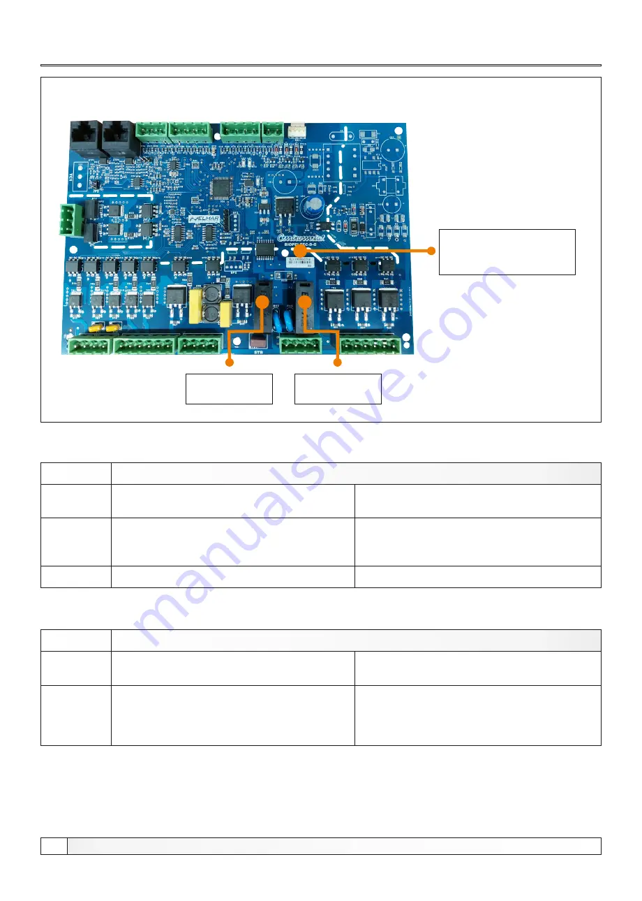
PCB:
BIOPELTEC-D-G (32861XXXXXXX G)
MARK
FUSE
DEVICES
F1
3,15 A, M
F2
3,15 A, M
- pumps P1, P2, P3
- controller (power supply)
- secondary air control motor
- primary air control motor
- mixing valve motor
PCB
: 32861XXXXXXX
MARK
FUSE
DEVICES
F1
3,15 A, M
F2
1,6 A, M
- pumps P1, P2, P3
- controller (power supply)
- fan
F3
3 15
,
A, M
- secondary air control motor
- primary air control motor
- mixing valve motor
- fan
Fuses
Technical instructions
BioTec Plus
44