


HI-PE multi-zone --- Rev.
FI 050 GB 60K10 v2_1
9
II - INSTALLATION
Before proceeding to install the device read the warnings and instructions in this section and in the
paragraph “
Installation, use and safety information
” carefully. Please note that CEIA is not responsible for
any damage that may result from installations that do not follow these guidelines.
Assembly
Unpacking the Metal Detector
Opening the packaging.
Cut the bands with scissors and
open the top side of the box.
Before taking out the components,
remove the staples that join the
strips of cardboard with pincers to
avoid injury or damage to the
equipment.
Handle the material with care during
unpacking operations, to avoid injury to
people or damage to the equipment.
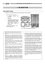
All accessories needed for assembly of
the Metal Detector are supplied with the
device
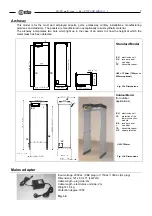
EU
CH
tr1
M
RX
TX
tr2
IK
PL
CA
PL
CA
customer address
EU
electronics
unit
IK
installation kit
M
manual
PL
list of materials
RX
receiver
panel
tr1
cross-bar
designed for
fixing the
electronics unit
tr2
second
cross-bar
TX
transmitter
panel
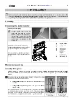
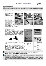
Mechanical assembly
Assembly of the probe
Refer to figures II-1a and II-1b. Connect the panels to the cross-bars
tr
, using the wrench provided to tighten
the screws
vt
fully (about 15 Nm). The transmitter panel (TX) can be recognised by the connector at the
bottom..
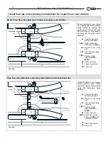
The probe can be assembles in two different configurations, both
having the same level of performance:
•
configuration A
(with TX panel on the left when facing the
exit side)
•
configuration B
(With TX panel on the right when facing
the exit side)
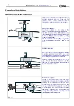
The choice between the two configurations should be made based
on installation requirements: see notes on the following pages (in
particular, the paragraphs “Application in an airport
environment”
and “Installation of coupled metal detectors - synchronisation”).
RX
TX
PSA
Configuration A
TX on left
RX
TX
PSA
Configuration B
TX on right


