


HI-PE multi-zone --- Rev.
FI 050 GB 60K10 v2_1
43
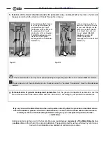
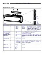
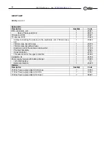
Electrical connections
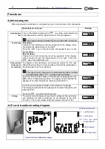
Fig. VII-1
A
B
C
H
K
F
D
E
Y
13 NC
12 NA
11 C
10 GND
9 GND/-B
8 ˜
7 +B/˜
6 SER.GND
5 PP1
4 INIB
3 BUSY
2 SER OUT
1 SER IN
J4
J3
J2
J1
Function
Connector
Pins
Description
Serial communication J1
6 - SER GND
3 - BUSY
2 - SER OUT
1 - SER IN
ground
busy line
data output
data input
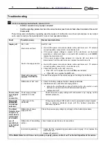
The BUSY line is used to monitor the
communication network between several Metal
Detectors; it is normally at "high" level (+5V); when
a Metal Detector effects a data transfer, the line
goes down to "low" level ( 0V ) and indicates to the
other devices that the network is busy.*
Photocells - monitoring
of the transits through
the gate (optional)
J1
6 - SER GND (ground)
5 - PP1
Contacts PP1-SER.GND on the J1 terminal board are connected to
two photocells p1, p2 (located on the antenna) .
N.B. manual reset is not available
Manual reset – alarm
memorisation
J1
6 - SER GND (ground)
5 - PP1
Connect a normally closed push-button: when an alarm occurs this
button keeps the output relay in alarm condition until it is
pressed
Indicator bar driver
J1
6 - SER GND (ground)
4 - INIB
Reserved
Relay
J2
11 - C (common)
12 - NA (norm. open)
13 - NC (norm. closed)
A switch contact NC-C-NA, where position NC coincides with the
normally closed contact and position NA with the normally open one
(closed when there is an alarm)..
Power supply
J2
10 GND
9 GND/-B
8 ˜
7 +B/˜
Reserved
Antenna connection
J4 - J3
A B C H K
F D E Y
Reserved


