background image

ENG

-38

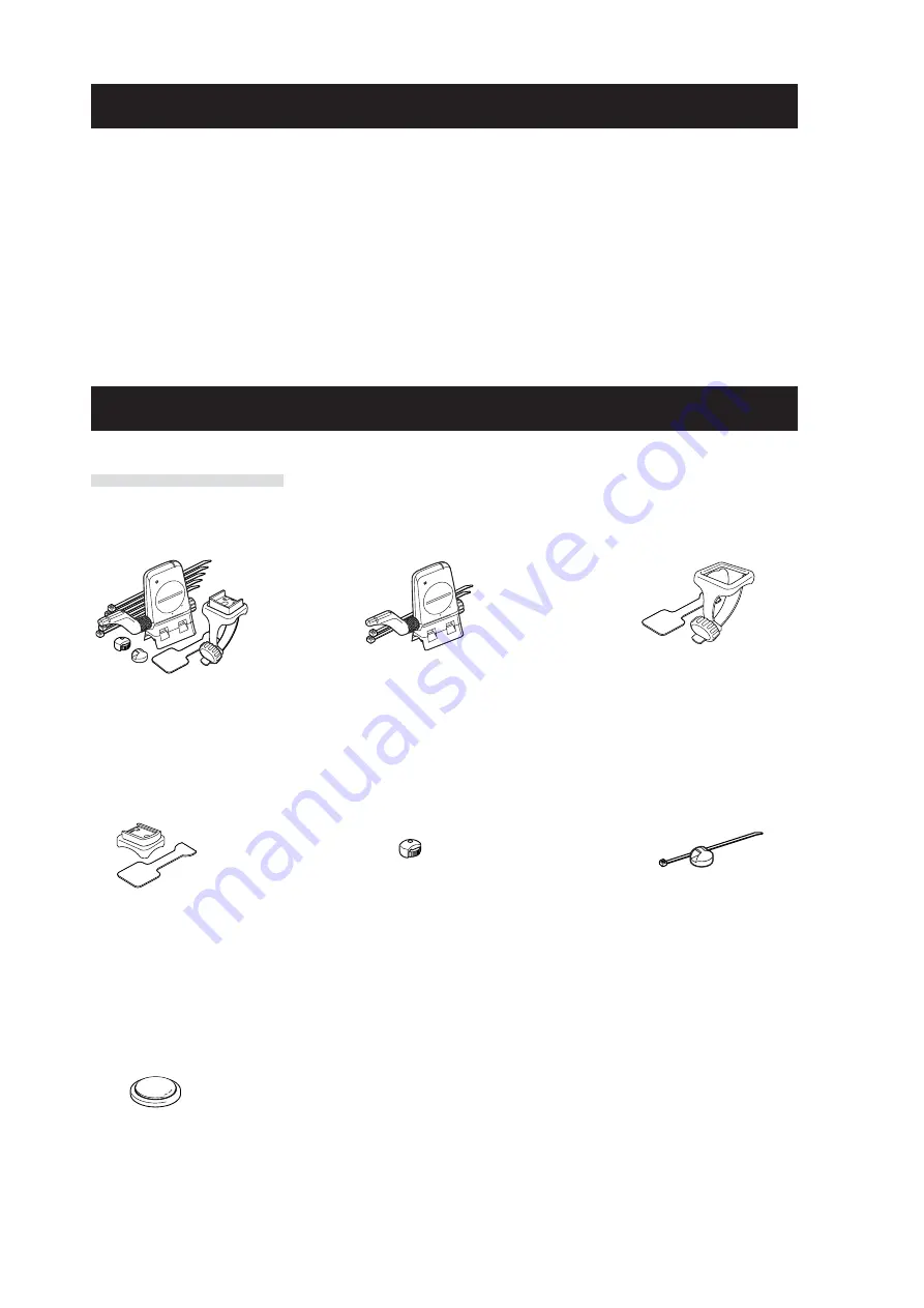
Spare accessories

Maintenance

Perform the daily care according to the following instructions.

• Regularly check that the positions of the magnets and sensors are correct, and they

are secured firmly.

• When the computer, and speed/cadence are dirty, wash them with water or wipe them

with a soft cloth dampened with diluted neutral detergent, then wipe with dry cloth.
Do not use solvents such as benzine or rubbing alcohol as they may damage the sur-
faces.

Standard accessories

#160-2380
Parts kit

#160-2385
Speed sensor kit

#160-0280
Bracket band

#160-2193
Bracket

#169-9691
Wheel magnet

#169-9766
Cadence magnet

#166-5150
Lithium battery (CR2032)

Summary of Contents for TR200DW280P

Page 1: ......

Page 2: ......

Page 3: ...product 1 How to install the unit on your bicycle See page 6 8 2 Preparing the computer See page 9 14 3 Basic operation of the computer See page 15 16 Measurement screen Please go here to learn how to...

Page 4: ...Backlight 16 Resetting the measurement data 16 Power saving function 16 Measurement screen 17 Upper and middle display data 17 Lower display data 18 Pace function 19 Lap function 19 Countdown distanc...

Page 5: ...ds of time Do not disassemble the computer or speed sensor Do not subject the computer or speed sensor to strong impact take care also to pre vent any of them from falling Do not use paint thinner or...

Page 6: ...acket Bracket band Speed sensor SPEED CADENCE Bracket rubber pad Wheel magnet Cadence magnet Nylon ties x5 Back light button LT Start stop enter button SSE Mode 1 button M1 Mode 2 button M2 Menu butto...

Page 7: ...cadence displays are maximum values Cadence pace arrow The pace arrows show whether the cur rent cadence is faster or slower than the average cadence Cadence unit Auto mode Lights up when the auto mo...

Page 8: ...length of the band with scissors Caution Round off the cut edge of the bracket band to prevent injury Bracket Bracket band Bracket rubber pad Stem Bracket Bracket band Bracket rubber pad Handlebar 1 A...

Page 9: ...move the speed sensor back and forth so that it is positioned properly After you move the speed sensor adjust the position so that the two magnets face the rel evant sensor zone 4 After adjustment ti...

Page 10: ...m falling Install Remove Click 2 3 Adjust the distance to the magnet 1 Adjust the distance between the wheel magnet and the SPEED side of the speed sensor to be about 3 mm After adjustment tighten the...

Page 11: ...re tained Selecting speed unit Set the sensor ID Tire circumference input Date clock setting Formatting operation Measurement screen Total time Total distance Menu screen File data saved Time format...

Page 12: ...on the screen the formatting operation has not been completed properly Perform the formatting operation again Restarting operation 1 Press the AC button on the back of the computer After all screen it...

Page 13: ...r Increase decrease M1 M2 Confirm SSE 3 Select the clock display format Select 24 hour or 12 hour using the M1 and M2 buttons and confirm with the SSE button 24h C C C C C 12h M1 M2 Confirm SSE 4 Ente...

Page 14: ...136 2146 2155 2130 2168 2180 2200 2288 2326 L mm 3 Tire circumference input Enter the tire circumference of the bicycle wheel in millimeter 1 Enter the last 2 digits of the tire circumference Enter us...

Page 15: ...ID page 28 4 Set the sensor ID Set the speed cadence sensor ID This unit requres the sensor ID in order for the computer to receive signal from the sensors To set the sensor ID be within 5 m from the...

Page 16: ...and adjust the position of the sensor and magnet again page 7 Important In the following situations it is possible that other sensor s ID was picked up such can happen when performing ID Synch at the...

Page 17: ...es of data which are switched by press ing the M1 and M2 buttons The display data are as follows Upper display data Displays the data related to the speed Middle display data Displays the data related...

Page 18: ...ays for about 3 seconds Pressing any button while backlight is still on extends the illumination for another 3 seconds Resetting the measurement data To reset the measurement data TM DST Lap Time C D...

Page 19: ...the time when you stop pedaling This feature produces actual averages which are different from those with conventional models that calculate it for the entire measurement time period 3 Average speed 1...

Page 20: ...ed in real time Displays the average lap speed of the current lap in real time 9 Lap timer Displays the elapsed time of the current lap in real time Trip lap distance in real time Displays the trip di...

Page 21: ...isplayed in the order as shown below and then return to the measurement screen Current speed Cadence 1 Average lap speed 2 Average lap cadence Displays the average lap speed average lap cadence from t...

Page 22: ...intervals and sectional trials such as hill climb section Countdown distance The countdown distance feature displays the countdown distance to a predetermined target trip distance and notifies when i...

Page 23: ...splays the target cadence zone status constant The target zone is turned on flashing The current cadence is out of the zone off The target zone is set to off The target cadence zone set from the menu...

Page 24: ...ENU Back Setting the measure ment unit Changing the measure ment unit MENU Back SSE page 30 File view Viewing and deleting files SSE page 23 Setting the clock date Changing the clock date SSE page 27...

Page 25: ...99 points no more files can be saved Viewing the measurement data in a file View the measurement data in a file saved in the computer 1 Press the MENU button in the measurement screen to switch to th...

Page 26: ...creation 1 Average speed 2 Average cadence 3 Trip distance 4 Elapsed time 5 Maximum speed 6 Maximum cadence 7 Upper zone limit 8 Lower zone limit 9 Time in the zone and the percentage 0 Time above th...

Page 27: ...ewing exiting lap data LAP 2 Switch the laps if applicable using the M1 and M2 buttons Switching the lap number M1 M2 3 Pressing the MENU button returns to the menu top screen FILE VIEW screen Pressin...

Page 28: ...file is deleted all lap data associated with that file is also deleted Once a file is deleted it cannot be restored Deleting files Delete the file saved in the computer You can select deleting only th...

Page 29: ...irm with the SSE button and then enter the Minute in the same way Increase decrease M1 M2 Confirm SSE 4 Select the date display format Select the date display format from YY MM DD MM DD YY and DD MM Y...

Page 30: ...nfirm with the SSE button Then enter the first 2 digits in the same way Increase decrease M1 M2 Move digits SSE 4 Pressing the MENU button returns to the menu top screen WHEEL screen and confirm the c...

Page 31: ...the change Pressing it again returns to the measurement screen To the menu top measurement screen MENU This unit enters the search mode for 5 minutes after starting the ID synch While ID SKIP is indic...

Page 32: ...nge s Pressing it again returns to the measurement screen To the menu top measurement screen MENU After the unit is switched the total distance measured in the past is automatically converted to the n...

Page 33: ...ng the menu M1 M2 Confirm SSE 2 Select On or OFF using the M1 and M2 buttons On C OFF M1 M2 3 Pressing the MENU button returns to the menu top screen AUTO MODE screen and confirm the change s Pressing...

Page 34: ...ess the MENU button on the measurement screen to switch to the menu top screen Switch to the SOUnD screen using the M1 and M2 buttons and confirm with the SSE button Menu top MENU Changing the menu M1...

Page 35: ...get cadence zone using the M1 and M2 buttons When using the target cadence zone select On confirm with the SSE button and then proceed to Step 3 When not using the target zone select OFF and then proc...

Page 36: ...to 80 and upper limit to 120 Then the computer emits an alarm when the cadence falls below 79 rpm or rises above 121 rpm Once the target zone is set to On the relevant data are recorded to the file an...

Page 37: ...sensor Is the Speed and Cadence sensor icon on Check whether the distance between the speed ca dence sensor and the mag net is too large Is the sensor zone of the speed cadence sensor off the center o...

Page 38: ...or is possibly depleted After replacing the battery with a new one CR2032 check the sensor ID again page 28 Lap data cannot be stored Have you already com pleted 99 laps Is the lap time over 100 hours...

Page 39: ...ck whether it seals correctly Computer Battery life Approx 1 years when used for 1 hour per day When the remaining battery capacity is low lights up 1 Remove the battery cover on the back of the compu...

Page 40: ...r and speed cadence are dirty wash them with water or wipe them with a soft cloth dampened with diluted neutral detergent then wipe with dry cloth Do not use solvents such as benzine or rubbing alcoho...

Page 41: ...bit one chip microcomputer crystal oscillator Display system Liquid crystal display EL backlight Speed Cadence sensor signal detection system Noncontact magnetic sensor Sensor signal transmission and...

Page 42: ...LIC OF IRELAND consumers please return to the place of purchase This does not affect your statutory rights Registration CATEYE Web Site http www cateye com For warranty service you must confirm your p...

Reviews: