


7
NOTE
: Range of electric heaters available is limited by model
number of the equipment installed. The Infinity Control will not
allow an electric heater size that is not supported by the installed
equipment.
Hydronic Heat Applications
The --B non--zoned model of the Infinity Control supports 2 types
of Hydronic Heat applications:
1. Hot water coil in combination with an FE fan coil and heat
pump, or hot water coil as sole heat source with an FE fan
coil.
2. Non--zoned FE fan coil combined with radiant hot water
heat.
In either application, a Hydronic Heat kit should be installed in
place of an electric heater. See FE fan coil Product Data for
accessory part number. The system will identify that Hydonic Heat
has been installed during the initial commissioning process. The
system will treat the hot water coil as either auxiliary heat in a heat
pump application, or the sole heat source. Setup options for
Hydronic Heat applications are described in the Setup section of
this instruction.
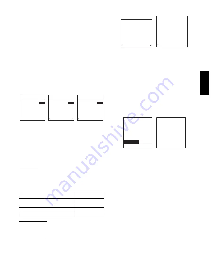
Selecting Accessories
ACCESSORIES
HUMIDIFIER
INSTALLED?
YES
PRESS +/- TO MAKE
SELECTION
BACK CONTINUE
ACCESSORIES
U.V. LIGHTS
INSTALLED?
YES
PRESS +/- TO MAKE
SELECTION
BACK CONTINUE
ACCESSORIES
AIR FILTER TYPE:
EAC
EAC
MEDIA
MEDIA + EAC
PRESS +/- TO MAKE
SELECTION
CONTINUE
AIR FILTER MEDIA TYPE
HUMIDIFIER INSTALLED?
U.V. LIGHTS INSTALLED?
A03198
Fig. 19 -- Accessories —UV Lights
Once the indoor and outdoor equipment have been found or
entered, the following screens will appear allowing the Installer to
select the “AIR FILTER TYPE; HUMIDIFIER INSTALLED”;
and “UV LIGHTS INSTALLED” (See Fig. 19). Use either Time or
Temp +/-- buttons to make appropriate selections in the highlighted
area on the display screen. Press right--side button to continue (or
advance) to the next screen.
Air Filter Type
This accessory screen will appear first. The installer will need to
enter the type of filter (MEDIA, EAC, or both). See Table 1 and
make a selection using Time or Temp +/-- button, then press
right--side button to continue.
Table 1 – Filter Selection
INSTALLED FILTER
MENU
SELECTION
1 inch to 4 inch media
MEDIA
High voltage EAC
EAC
High voltage EAC + 1 to 4 inch media
MEDIA + EAC
Infinity Air Purifier
MEDIA
Humidifier Installed
This will appear after the Air Filter Type screen. Select whether a
humidifier is installed on the system, YES or NO, then press
right--side button to continue.
UV Lights Installed
This screen will appear to select whether UV lights are installed on
the system, select YES or NO, then press right--side button to
continue.
Equipment Summary
EQUIPMENT SUMMARY
FURNACE
58MVB0100-12
AC
24ANA136A003
FILTER
EAC
HUMIDIFIER
YES
UV LIGHTS
YES
NO YES
SETUP
COMPLETE!
SAVE
ALL SELECTIONS/
NO YES
A07247
Fig. 20 -- Equipment Summary
The “EQUIPMENT SUMMARY” screen will appear after
Accessories have been selected. This screen will give a summary of
all equipment automatically found or manually selected. If a wrong
selection was made, press left--side button (BACK selection) to go
back to that particular screen and make changes. When everything
is OK, press right--side button again to continue. (See Fig. 20.)
The “SETUP COMPLETE! SAVE ALL SELECTIONS?” screen
will appear after Equipment Summary. To Save All Selections
press (YES) right--side button. Pressing the left--side button (NO
selection) will return to the Equipment Summary screen where
changes can be performed to any of the equipment selection
screens. After selecting YES, the initial power up sequence of the
new Infinity Control is complete.
Static Pressure Check
STATIC
PRESSURE
CHECK
PLEASE WAIT
EXTERNAL STATIC
PRESSURE
MEASURED:
0.72 INCHES
AT 1200 CFM
CONTINUE >
A05000
Fig. 21 -- Static Pressure Check
This screen will appear after Setup is exited. The system will
perform a static pressure check. This process will take about 1 1/2
minutes to complete. When completed, a screen will appear
displaying the static pressure (in inches) across the equipment at
the expected highest delivered airflow. If the static pressure is over
1 inch, a warning will appear, but equipment operation and the
TrueSense
t
dirty filter detection operation will not be affected.
NOTE
: The static pressure check occurs only at initial installation,
or when INSTALL is run in the INSTALL/SERVICE menu.
QUICK START
For first time installers, Quick Start will allow a quick start up of
the Infinity System before learning all the details of system
operation. However, for the best possible comfort and operation
refer to the Infinity Control Owner’s Manual.
Set Day, Time & Desired Humidity
1. Flip down the door at the base of the Infinity Control and
press the
BASIC
button.
2. Adjust the highlighted
HOUR
setting using the
TIME
(+/--) button.
3. Press
SCROLL
button (down) to highlight
MINUTE
.
4. Adjust the
MINUTE
setting using the
TIME
(+/--) button.
5. Press
SCROLL
button (down) to highlight
DAY
.
6. Adjust the current
DAY
setting using the
TIME
(+/--) but-
ton.
7. Press
SCROLL
button (down) to highlight
HUMIDITY
.
CCUI
D
01
--
B


