


6
transformer. Applying 24VAC isolation relay coil to furnace or fan
coil HUM and COM terminals will allow the Infinity Control to
automatically energize the HUM output during a call for
humidification. The N.O. relay contacts will be used to energize the
humidifier. See fan powered humidifier installation instructions for
more details.
EQUIPMENT HAZARD
Failure to follow this caution may result in equipment damage.
Do not apply 24VAC fan powered humidifier (with internal
power supply) direct to indoor unit HUM and COM terminals.
CAUTION
!
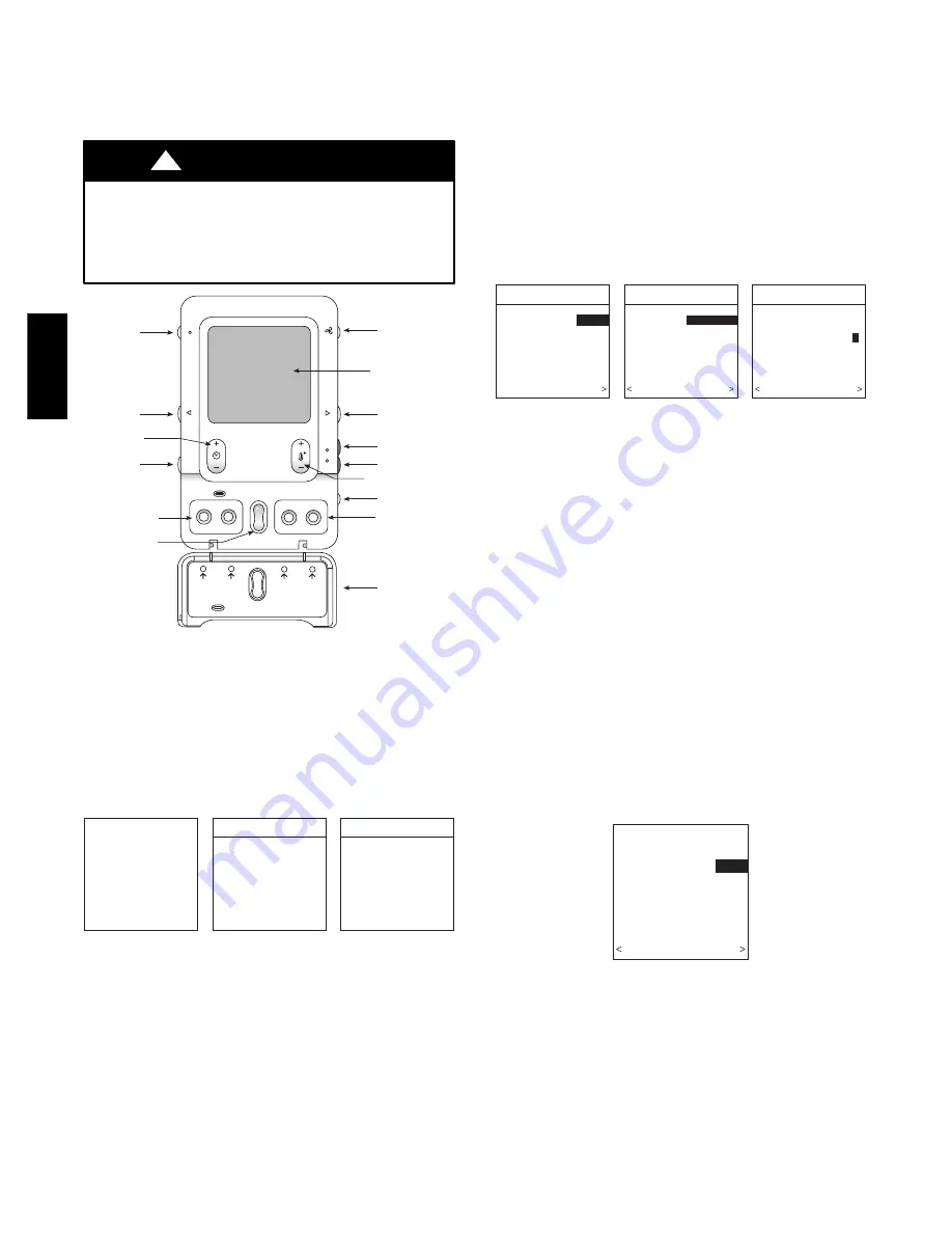
HOLD
COOL
HEAT
SCHEDULE
VACATION
PROGRAM
SCROLL
BASIC
ADVANCED
SETUPS
Schedule
to program
temperature
schedule
Vacation
to start/end
vacation
Basic
to set time,
humidity
Advanced
for all other
settings
Scroll
up & down
Fan Button
Display Screen
(LCD)
Right-Side
Button
Heat Button
Cool Button
Temperature
(+/-) Button
System
On/Off Button
Basic & Advanced
Setup Buttons
Flip Down
Door
Left-Side
Button
Humidity/OAT
Button
Hold
Button
Time (+/-)
Button
Schedule & Vacation
Program Buttons
Up/Down
Scroll Buttons
A03194
Fig. 15 -- Functional Overview
INITIAL POWER--UP
NOTE
: Refer to Functional Overview (see Fig. 15) to become
familiar with key function buttons such as “System On/Off,”
“Fan,” “Left--Side” and “Right--Side” buttons, etc. These function
buttons will be used frequently during setup.
Power Up Sequence
ESTABLISHING
COMMUNICATIONS
WITH EQUIPMENT
PLEASE WAIT
SOFTWARE
VERSION
INDOOR UNIT
SEARCHING FOR
INDOOR EQUIPMENT
WORKING
OUTDOOR UNIT
SEARCHING FOR
OUTDOOR EQUIPMENT
WORKING
A03195
Fig. 16 -- Power Up Sequence
This section addresses initial power up (or commissioning) of a
new Infinity Control. The User Interface will communicate and
identify all Infinity components in the system. The following is a
typical example for a communicating Variable--Speed Furnace /
Fan Coil with a 2--stage Air Conditioner / Heat Pump (including
Hybrid Heat).
The User Interface display will light up and indicate that it is now
“ESTABLISHING COMMUNICATIONS WITH EQUIPMENT
PLEASE WAIT”. The User Interface will automatically continue
by
“SEARCHING
FOR
EQUIPMENT”,
followed
by
“SEARCHING FOR OUTDOOR EQUIPMENT” (see Fig. 16).
Once the indoor and outdoor equipment has been found, the
Installer will be asked to select Accessories. Packaged Products
will be automatically identified and the Installer will be asked to
select Accessories. Proceed to Selecting Accessories.
NOTE
: If the variable--speed indoor equipment (furnace or fan
coil) cannot be found, the User Interface will display “CANNOT
COMMUNICATE WITH INDOOR UNIT”. This MUST be
corrected before the initial power up sequence can continue. If
indoor unit is found, but outdoor unit is not found, “OUTDOOR
UNIT NOT IDENTIFIED” will appear. Proceed to the next section
for Outdoor Unit Identification.
Selecting Outdoor Unit
OUTDOOR UNIT
NOT IDENTIFIED
SELECT TYPE:
NONE
NONE, AC, HP
PRESS +/- TO MAKE
SELECTION
CONTINUE
OUTDOOR UNIT
ENTER HEAT PUMP
SIZE
36000 BTU
18000 TO 60000 BTU
PRESS +/- TO MAKE
SELECTION
BACK CONTINUE
OUTDOOR UNIT
HEAT PUMP
ENTER NUMBER OF
SPEEDS, 1 or 2:
1
PRESS +/- TO MAKE
SELECTION
BACK CONTINUE
A03196
Fig. 17 -- Selecting Outdoor Unit
If there is no communicating outdoor unit, the screen, shown in
Fig. 17, will appear. Press either Time or Temp +/-- buttons to
select AC (air conditioner), HP (heat pump), or None (no unit
installed). Press right--side button to continue to next screen.
If either AC or HP has been selected as the outdoor unit type, the
middle screen will appear (see Fig. 17). Press either Time or Temp
+/-- buttons to select appropriate BTU size of outdoor unit, then
press right side button to continue. If a NIM (Network Interface
Module) is applied for non--communicating two--stage outdoor
equipment, select 1 or 2--stage compressor operation, and press
right--side button to continue.
NOTE
: Range of outdoor unit BTU selection is limited by model
number of indoor unit installed. The Infinity Control will not allow
an outdoor unit size that is not supported by the installed indoor
unit.
NOTE
: On new system installations, the model and serial number
will be recognized and displayed. On any indoor/outdoor board
replacements, the equipment will be recognized but the exact
model/serial number will not be displayed.
Selecting Electric Heater
ELECTRIC HEATER
NOT IDENTIFIED
ENTER SIZE:
5 KW
NONE, 5,10,15 KW
PRESS +/- TO MAKE
SELECTION
BACK CONTINUE
A03197
Fig. 18 -- Selecting Electric Heater
If the equipment is a fan coil, packaged heat pump, or packaged
AC and the electric heater is not self--identifying, “ELECTRIC
HEATER NOT IDENTIFIED” will appear (see Fig. 18). Press
either Time or Temp +/-- buttons to select appropriate size of
electric heater installed, then press right--side button to continue.
An asterisks (*) will appear next to electric heater sizes that may
cause excessive airflow.
CCUI
D
01
--
B


