background image

28

MAINTENANCE

To ensure continuing high performance and to minimize the

possibility of premature equipment failure, periodic maintenance
must be performed on this equipment. This combination

heating/cooling unit should be inspected at least once each year by
a qualified service person. To troubleshoot cooling or heating of

units, refer to Tables 10, 11 and 12.

NOTE

: Consult your local dealer about the availability of a

maintenance contract.

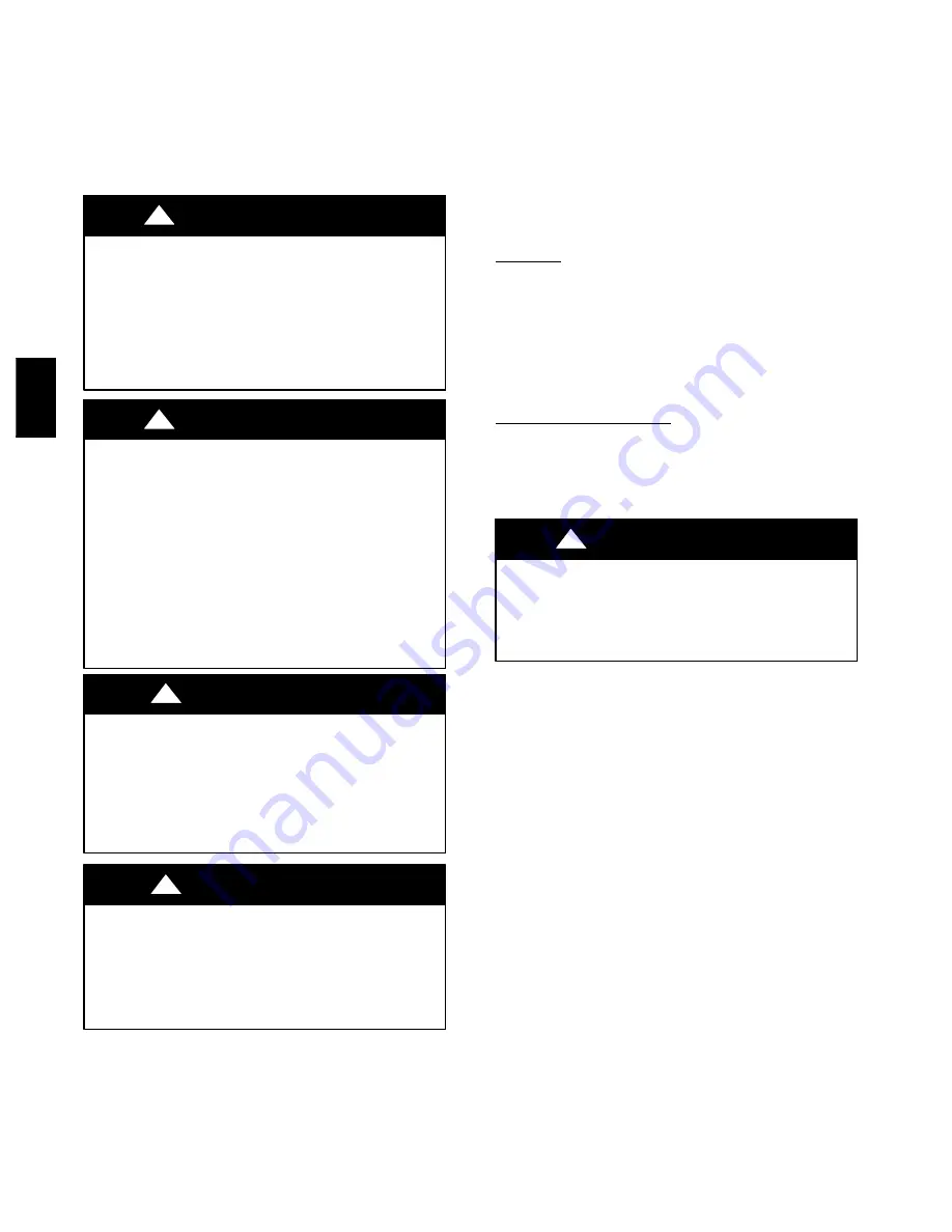
PERSONAL INJURY AND UNIT DAMAGE HAZARD

Failure to follow this warning could result in personal injury

or death and unit component damage.
The ability to properly perform maintenance on this

equipment requires certain expertise, mechanical skills, tools

and equipment. If you do not possess these, do not attempt to

perform any maintenance on this equipment, other than those

procedures recommended in the Owner’s Manual.

!

WARNING

ELECTRICAL SHOCK AND EXPLOSION HAZARD

Failure to follow these warnings could result in personal

injury or death:

1. Turn off electrical power to the unit and install a lockout

tag before performing any maintenance or service on this
unit.

2. Use extreme caution when removing panels and parts.
3. Never place anything combustible either on or in contact

with the unit.

4. Should overheating occur or the gas supply fail to shut

off, turn off external main manual gas valve to the unit.

Then shut off electrical supply.

!

WARNING

CUT HAZARD

Failure to follow this caution may result in personal injury.
When removing access panels (see Fig. 19) or performing

maintenance functions inside your unit, be aware of sharp

sheet metal parts and screws. Although special care is taken

to reduce sharp edges to a minimum, be extremely careful

when handling parts or reaching into the unit.

CAUTION

!

UNIT OPERATION HAZARD

Failure to follow this caution may result in improper

operation.
Errors made when reconnecting wires may cause improper

and dangerous operation. Label all wires prior to

disconnecting when servicing.

CAUTION

!

The minimum maintenance requirements for this equipment are as
follows:

1. Inspect air filter(s) each month. Clean or replace when

necessary. Certain geographical locations may require more

frequent inspections.

2. Inspect indoor coil, outdoor coil, drain pan, and condensate

drain each cooling season for cleanliness. Clean when

necessary.

3. Inspect blower motor and wheel for cleanliness at the

beginning of each heating and cooling season. Clean when

necessary. For first heating and cooling season, inspect
blower wheel bi--monthly to determine proper cleaning
frequency.

4. Check electrical connections for tightness and controls for

proper operation each heating and cooling season. Service

when necessary. Ensure electrical wiring is not in contact
with refrigerant tubing or sharp metal edges.

5. Check and inspect heating section before each heating

season. Clean and adjust when necessary.

6. Check flue hood and remove any obstructions, if necessary.

Air Filter

IMPORTANT

: Never operate the unit without a suitable air filter

in the return--air duct system. Always replace the filter with the
same dimensional size and type as originally installed. (See Table 1
for recommended filter sizes.)
Inspect air filter(s) at least once each month and replace

(throwaway--type) or clean (cleanable--type) at least twice during
each heating and cooling season or whenever the filter(s) becomes

clogged with dust and/or lint.

Indoor Blower and Motor

NOTE

: All motors are prelubricated. Do not attempt to lubricate

these motors.
For longer life, operating economy, and continuing efficiency,

clean accumulated dirt and grease from the blower wheel and

motor annually.

ELECTRICAL SHOCK HAZARD

Failure to follow this warning could result in personal injury

or death.
Disconnect and tag electrical power to the unit before cleaning

and lubricating the blower motor and wheel.

!

WARNING

Cleaning the Blower Motor and Wheel

1. Remove and disassemble blower assembly as follows:

a. Remove blower access panel (see Fig. 19).

b. Disconnect 5 pin plug and 4 pin plug from indoor

blower motor. Remove capacitor if required.

c. On all units, remove blower assembly from unit.

Remove screws securing blower to blower partition and
slide assembly out. Be careful not to tear insulation in

blower compartment.

d. Ensure proper reassembly by marking blower wheel and

motor in relation to blower housing before disassembly.

e. Loosen setscrew(s) that secures wheel to motor shaft.

Remove screws that secure motor mount brackets to

housing, and slide motor and motor mount out of
housing.

2. Remove and clean blower wheel as follows:

a. Ensure proper reassembly by marking wheel orientation.

b. Lift wheel from housing. When handling and/or

cleaning blower wheel, be sure not to disturb balance

weights (clips) on blower wheel vanes.

c. Remove caked--on dirt from wheel and housing with a

brush. Remove lint and/or dirt accumulations from

wheel and housing with vacuum cleaner, using soft
brush attachment. Remove grease and oil with mild

solvent.

d. Reassemble wheel into housing.

e. Reassemble motor into housing. Be sure setscrews are

tightened on motor shaft flats and not on round part of
shaft. Reinstall blower into unit. Reinstall capacitor.

48E

Z

--

A

Summary of Contents for 48EZ(N) - A

Page 1: ...Limit Switch 29 Burner Ignition 29 Main Burners 29 Outdoor Coil Indoor Coil Condensate Drain Pan 29 A09034 Fig 1 Unit 48EZ A Outdoor Fan 30 Electrical Controls and Wiring 30 Refrigerant Circuit 30 Ga...

Page 2: ...ms against shipping list Immediately notify the nearest equipment distribution office if any item is missing To prevent loss or damage leave all parts in original packages until installation If the un...

Page 3: ...3 A09450 Fig 2 48EZ A24 36 Unit Dimensions 48EZ A...

Page 4: ...4 A09451 Fig 3 48EZ A42 60 Unit Dimensions 48EZ A...

Page 5: ...S 1 Roof curb must be set up for unit being installed 2 Seal strip must be applied as required to unit being installed 3 Roof curb is made of 16 gauge steel 4 Attach ductwork to curb flanges of duct r...

Page 6: ...t recirculate to the condenser coil Do not locate the unit in either a corner or under an overhead obstruction The minimum clearance under a partial overhang such as a normal house overhang is 48 in 1...

Page 7: ...verflowing Prime the trap with water Connect a drain tube using a minimum of 3 4 in PVC or 3 4 in copper pipe all field supplied at the outlet end of the 2 in 51 mm trap Do not undersize the tube Pitc...

Page 8: ...supply pipe within 6 ft 1 8 m of heating section 6 Install ground joint union close to heating section between unit manual shutoff and external manual main shut off valve 7 Pressure test all gas pipi...

Page 9: ...3 7 3 17 3 7 3 17 4 7 3 17 4 7 INDOOR BLOWER Nominal Cooling Airflow CFM Size in mm Motor hp 800 10x10 254x254 1 2 800 10x10 254x254 1 2 1000 10x10 254x254 1 2 1000 10x10 254x254 1 2 1200 11x10 279x2...

Page 10: ...ceed 0 08 IN W C If using accessory filter rack refer to filter rack installation instructions for correct filter size and quantity Table 2 Maximum Gas Flow Capacity NOMINAL IRON PIPE SIZE IN INTERNAL...

Page 11: ...amage to the unit being installed When cutting duct panels do not contact or damage any internal components heat exchanger electric heat Do not use a saw blade that protrudes more than 1 in 25 mm into...

Page 12: ...y Knockout Basepan Downflow Vertical Return Knockout A09060 Fig 8 Supply and Return Duct Opening Return Duct Panels Return Supply Duct Panels from Underside of Base Alternate Method Supply Duct Panels...

Page 13: ...nd Fig 10 for reference when making high voltage connections Proceed as follows to complete the high voltage connections to the unit Single phase units 1 Run the high voltage L1 L2 and ground lead int...

Page 14: ...thstand a 30 sec overload or shorted secondary condition If an overload or short is present correct overload condition and check for blown fuse on gas control board or Interface Fan Board Replace fuse...

Page 15: ...before the time delay has expired 2 T2 energizes the compressor contactor via the High Pressure Switch HPS and Low Pressure Switch LPS The compressor and outdoor fan start Thermostat G energizes the...

Page 16: ...DERATE MULTIPLIER FACTOR 0 2000 0 610 0 1 00 2001 3000 610 914 8 12 0 90 3001 4000 315 1219 12 16 0 86 4001 5000 1220 1524 16 20 0 82 5001 6000 1524 1829 20 24 0 78 6001 7000 1829 2134 24 28 0 74 7001...

Page 17: ...ormal Operation An LED light emitting diode indicator is provided on the integrated gas unit controller IGC to monitor operation The IGC is located by removing the control access panel see Fig 19 Duri...

Page 18: ...abnormal condition exists somewhere in the cooling system such as insufficient airflow across either coil or both coils CAUTION Proceed as follows 1 Remove caps from low and high pressure service fit...

Page 19: ...wire from the LOW terminal on the interface fan board IFB See Fig 14 2 Determine correct normal cooling fan speed for unit and application Add the wet coil pressure drop in Table 8 to the system stati...

Page 20: ...WIRE COLOR EXTERNAL STATIC PRESSURE in W C 0 1 0 2 0 3 0 4 0 5 0 6 0 7 0 8 0 9 48EZ N A24040 30 60oF 17 33oC Low Blue CFM 754 650 538 429 Heating Rise oF 40 46 56 NA NA NA NA NA NA Heating Rise oC 22...

Page 21: ...665 538 451 Heating Rise oF 46 50 54 NA NA NA NA NA NA Heating Rise oC 25 28 30 NA NA NA NA NA NA Medium Red CFM 1088 1023 954 881 800 723 658 563 461 Heating Rise oF 41 43 47 50 NA NA NA NA NA Heatin...

Page 22: ...CFM 1345 1282 1235 1194 1140 1095 1027 974 921 Heating Rise oF 33 35 36 37 39 41 43 46 48 Heating Rise oC 18 19 20 21 22 23 24 25 27 Medium Red CFM 1505 1452 1413 1358 1323 1282 1234 1169 1130 Heating...

Page 23: ...nk CFM 1457 1404 1367 1318 1284 1233 1197 1144 1104 Heating Rise oF 60 NA NA NA NA NA NA NA NA Heating Rise oC 33 NA NA NA NA NA NA NA NA Medium2 Red CFM 1736 1695 1642 1601 1553 1512 1465 1427 1381 H...

Page 24: ...8 49 49 51 51 53 Heating Rise oC 25 26 26 26 27 27 28 29 29 Med High1 Orange CFM 2131 2088 2065 2013 1982 1941 1888 1860 1785 Heating Rise oF 41 42 42 43 44 45 46 47 49 Heating Rise oC 23 23 23 24 24...

Page 25: ...25 A09068 Fig 15 208 230 1 60 Wiring Diagram Unit 48EZ A 48EZ A...

Page 26: ...26 A09209 Fig 16 208 230 3 60 Wiring Diagram Unit 48EZ A 48EZ A...

Page 27: ...27 A08019 Fig 17 Cooling Charging Table Subcooling 48EZ A...

Page 28: ...pect blower wheel bi monthly to determine proper cleaning frequency 4 Check electrical connections for tightness and controls for proper operation each heating and cooling season Service when necessar...

Page 29: ...Table 5 in these instructions for LED interpretation If lockout occurs unit may be reset by either momentarily interrupting power supply to unit or by turning selector switch to OFF position at the t...

Page 30: ...l controls and wiring annually Be sure to turn off the gas supply and then the electrical power to the unit Remove access panels see Fig 19 to locate all the electrical controls and wiring Check all e...

Page 31: ...supply and return air grilles are open and free from obstructions and that the air filter is clean When necessary refer to the Indoor Airflow and Airflow Adjustments section to check the system airfl...

Page 32: ...rigerant The compressor used in this product is specifically designed to operate with Puron R 410A refrigerant and cannot be interchanged The compressor is an electrical as well as mechanical device E...

Page 33: ...s Puron R 410A refrigerant which has higher operating pressures than R 22 and other refrigerants No other refrigerant may be used in this system Gauge set hoses andrecoverysystemmustbe designedto hand...

Page 34: ...dip tube charge Puron units with cylinder in upright position and a commercial metering device in manifold hose Charge refrigerant into suction line TROUBLESHOOTING Use the Troubleshooting Guides See...

Page 35: ...restriction and remove Compressor operates continuously Dirty air filter Replace filter Unit undersized for load Decrease load or increase unit size Thermostat set too low Reset thermostat Low refrig...

Page 36: ...n of the indoor evaporator fan motor Ensure that the supply air temperature rise is in accordance with the range on the unit nameplate Clean or replace filters Flame sense fault LED 3 flashes The IGC...

Page 37: ...N IS LEVEL CHECK FAN WHEEL AND PROPELLER FOR LOCATION IN HOUSING ORIFICE AND SETSCREW TIGHTNESS III START UP ELECTRICAL SUPPLY VOLTAGE COMPRESSOR AMPS INDOOR EVAPORATOR FAN AMPS TEMPERATURES OUTDOOR C...

Page 38: ...S 7310 W Morris St S Indianapolis IN 46231 Edition Date 08 09 Manufacturer reserves the right to change at any time specifications and designs without notice and without obligations Catalog No 48EZ 0...

Reviews: