


Reviews:
No comments
Related manuals for CTXG09QVJUW
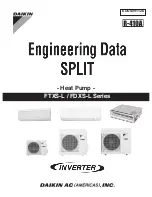
SUPER MULTI NX FDXS09LVJU
Brand: Daikin Pages: 206

MFZ-KJ25VE
Brand: Mitsubishi Electric Pages: 12
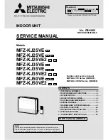
MFZ-KJ25VE
Brand: Mitsubishi Electric Pages: 40
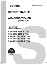
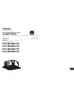
RAV-SM1104UTP-E (TR)
Brand: Toshiba Pages: 108
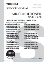
RAV-SM1104UTP-E (TR)
Brand: Toshiba Pages: 56
LW1214HR
Brand: LG Pages: 48
PCFY-P VGM-E
Brand: Mitsubishi Electric Pages: 200
PCFY-P VGM-E
Brand: Mitsubishi Electric Pages: 68
PEA-RP200 GA
Brand: Mitsubishi Electric Pages: 16
PEA-RP200 GA
Brand: Mitsubishi Electric Pages: 184
PEA-RP400 GA
Brand: Mitsubishi Electric Pages: 22
PKA-RP HAL
Brand: Mitsubishi Electric Pages: 108
PKA-RP HAL
Brand: Mitsubishi Electric Pages: 224
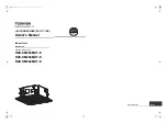
RAV-SM404MUT-E
Brand: Toshiba Pages: 288
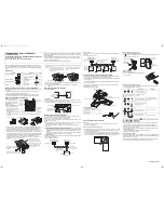
RAV-SM404MUT-E
Brand: Toshiba Pages: 121
RAV-SM404MUT-E
Brand: Toshiba Pages: 16
RBC-AX32U(W)-E
Brand: Toshiba Pages: 1
RBC-AX32U(W)-E
Brand: Toshiba Pages: 16


