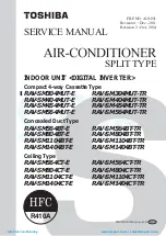
Toshiba RAV-SM1104UTP-E (TR), Service Manual
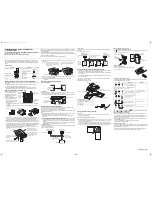
The Toshiba RAV-SM1104UTP-E (TR) is a top-quality air conditioning unit that guarantees optimal comfort in any space. Ensure smooth installation and operation with our comprehensive Installation Manual. Download it for free from our website manualshive.com and discover step-by-step instructions to effortlessly set up and enjoy this outstanding product.
Share
Download


Reviews:
No comments
Related manuals for RAV-SM1104UTP-E (TR)

CTXG09QVJUW
Brand: Daikin Pages: 254
SUPER MULTI NX FDXS09LVJU
Brand: Daikin Pages: 206

MFZ-KJ25VE
Brand: Mitsubishi Electric Pages: 12
MFZ-KJ25VE
Brand: Mitsubishi Electric Pages: 40
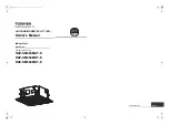
RAV-SM1104UTP-E (TR)
Brand: Toshiba Pages: 56
LW1214HR
Brand: LG Pages: 48
PCFY-P VGM-E
Brand: Mitsubishi Electric Pages: 200
PCFY-P VGM-E
Brand: Mitsubishi Electric Pages: 68
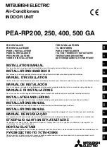
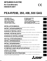
PEA-RP200 GA
Brand: Mitsubishi Electric Pages: 16
PEA-RP200 GA
Brand: Mitsubishi Electric Pages: 184
PEA-RP400 GA
Brand: Mitsubishi Electric Pages: 22
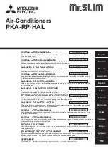
PKA-RP HAL
Brand: Mitsubishi Electric Pages: 108
PKA-RP HAL
Brand: Mitsubishi Electric Pages: 224
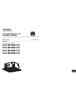
RAV-SM404MUT-E
Brand: Toshiba Pages: 288
RAV-SM404MUT-E
Brand: Toshiba Pages: 121
RAV-SM404MUT-E
Brand: Toshiba Pages: 16
RBC-AX32U(W)-E
Brand: Toshiba Pages: 1
RBC-AX32U(W)-E
Brand: Toshiba Pages: 16


