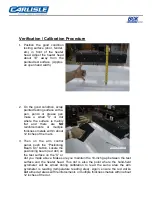
Verification / Calibration Procedure
1.
Position the good condition
testing surface (door, fender,
etc.) in front of the heater
head. Adjust the heater head
about 10” away from the
painted test surface. (Approx.
an open hand width.)
2. On the good condition, scrap
painted testing surface with a
pen, pencil or grease pen
make a small “X” or dot
where the surface is mainly
flat and there are
NO
reinforcements or multiple
thickness metals within about
12 inches of the mark.
3. Then on the arm control
panel, push the “Positioning
Beam On” button. Locate the
positioning beam (red dot) on
the test surface on the “X” or
dot you made above. Make sure you maintain the 10-inch gap between the test
surface and the heater head. This dot is also the point where the hand-held
pyrometer will be aimed during calibration to read the same area the arm
pyrometer is reading (temperature reading area). Again, ensure the red dot
is
not
aimed at areas with reinforcements or multiple thickness metals within about
12 inches of the dot.
Summary of Contents for BGK AutoCure 6000-2216
Page 1: ...AutoCure 6000 2216 Overhead Heater Assembly and Operating Manual ...
Page 22: ......
Page 23: ......
Page 37: ......
Page 38: ......
Page 41: ...A DETAIL J SCALE0 40 1 REMOVET1 11SBOLTAFTERINSTAI I ATION ...
Page 43: ......
Page 44: ......
Page 45: ......
Page 46: ......
Page 47: ...AUTOCURE MODEL NUMBER AC6 2216 480 SP ...
Page 48: ......
Page 49: ......

