


1.1 Connessioni
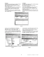
Alle connessioni WebGate si accede dal retro dell’unita, come illustrato
nella figura qui sotto:
1.
interfaccia Ethernet 10BaseT a rete locale (LAN)
2.
interfaccia RS232 DTE a consolle locale
3.
interfaccia RS485 a rete Carel, utilizzata per i collegamenti ai
dispositivi Carel
4.
connettore per adattatore da 18VAC (installazione su tavolo)
5.
connettore per alimentazione da 24VAC (montaggio a pannello)
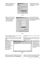
Per il collegamento del WebGate è necessario osservare le
seguenti AVVERTENZE:
1.
Una tensione di alimentazione elettrica diversa da quella prescritta
può danneggiare seriamente il sistema.
2.
Utilizzare capicorda adatti ai morsetti. Allentare ciascuna vite ed
inserirvi i capicorda, quindi serrare le viti. Ad operazione ultimata,
tirare leggermente i cavi per verificarne il corretto serraggio.
3.
Evitare di avvicinarsi con le dita ai componenti elettronici montati
sulle schede per evitare scariche elettrostatiche (estremamente
dannose) dall'operatore ai componenti.
4.
Separare quanto più possibile i cavi dei segnali dai cavi di potenza
per evitare possibili disturbi elettromagnetici. Non inserire mai cavi di
potenza (compresi i cavi dell’alimentazione principale) e cavi RS485,
RS232 o Ethernet nelle stesse canaline.
5.
Non cercare di smontare l’unità o di modificarla in alcun modo,
perchè questo può comportare il rischio di incendio e di scossa.
1.1.1 Collegamento al cavo Ethernet
Il WebGate utilizza un connettore RJ45 per Ethernet 10BaseT 10Mb/s.
Per il collegamento ad un hub o ad uno switch utilizzare un cavo patch.
Per il collegamento diretto a PC utilizzare un cavo cross.
1.1.2 Collegamento all’interfaccia RS232
Il WebGate è dotato di un interfaccia standard di tipo DTE, con
connettore maschio DB-9 a 9 vie: la tabella che segue illustra i segnali
standard RS232:
Pin
Sigla
Nome completo
Direzione
1
CD
CARRIER DETECT
Da DCE
2
RD
RECEIVE DATA
Da DCE
3
TD
TRANSMIT DATA
A DCE
4
DTR
DATA TERMINAL READY
A DCE
5
SG
SIGNAL GROUND
---
6
DSR
DATA SET READY1
Da DCE
7
RTS
REQUEST TO SEND
A DCE
8
CTS
CLEAR TO SEND1
Da DCE
9
RI
RING INDICATOR2
Da DCE
Tab. 1.1.2.1
1
Questi pin possono non essere collegati in alcuni modelli WebGate
2
Questo pin non è collegato in nessun modello WebGate.
1.1 Connections
WebGate connections are accessible from the back panel of the unit,
as indicated below:
1.
Ethernet 10BaseT connector to corporate LAN.
2.
RS232 DTE interface to connect a local console
3.
RS485 interface to Carel Network, used to connect the Carel devices
4.
Plug connector for the 18VAC power adapter (desktop installation)
5.
Connector for the 24VAC power supply (panel mounting)
When connecting WebGate the following WARNINGS should be
heeded:
1.
Voltages different from the power ratings will seriously damage the
system.
2.
Use cable-ends which are suitable for the terminals being used.
Loosen each screw and insert the cable-end, then tighten the
screws. On completing the operation lightly tug the cables to check
that they are correctly inserted.
3.
Avoid touching or nearly-touching electronic components mounted
on the boards to avoid electrostatic discharges (extremely
damaging) from the operator to the components.
4.
Separate as much as possible the signal cables from any power
cables to avoid possible electromagnetic influence. Never insert
power cables (including mains cables) and RS485, RS232 or
Ethernet cables in the same channels.
5.
Never try to disassemble the unit or modify it in any way, because
this may cause fire and electric shock.
1.1.1 Connection of the Ethernet cable
WebGate uses a RJ45, 10BaseT connector, 10Mb/s interface. When
connecting to a hub or switch use a straight cable patch. When
connecting directly to a PC use a cross cable instead.
1.1.2 Connection of the RS232 interface
WebGate is provided with a standard DTE interface with a 9 pin male
DB-9 connector: In the following table are depicted the standard RS232
signals:
Pin No
Abbreviation
Description
Direction
1
CD
CARRIER DETECT
From DCE
2
RD
RECEIVE DATA
From DCE
3
TD
TRANSMIT DATA
To DCE
4
DTR
DATA TERMINAL READY
To DCE
5
SG
SIGNAL GROUND
---
6
DSR
DATA SET READY1
From DCE
7
RTS
REQUEST TO SEND
To DCE
8
CTS
CLEAR TO SEND1
From DCE
9
RI
RING INDICATOR2
From DCE
Tab. 1.1.2.1
1
These pins may be unconnected in some WebGate models
2
This pin is unconnected in all WebGate models.
5
Manuale WebGate - cod. +030220230 rel. 1.0 - 16.09.2003
1
2
3
4
5
Fig. 1.1.1