


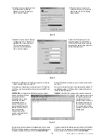
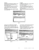

Per collegare il WebGate ad un PC va utilizzato
un cavo schermato null-modem. Sono
necessarie solo le linee TD, RD e SG. Si ricordi
che, poiché il PC e il WebGate sono dotati di
interfaccia DTE, le linee TD e RD devono
essere scambiate:
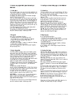
1.1.3 Collegamento all’interfaccia RS485
Il cavo di connessione del WebGate con le periferiche Carel in RS485
che Carel consiglia è:
• a 2 fili ritorti,
• schermato, preferibilmente con filo di continuità,
• di sezione AWG20 (0,5 mm2) o AWG22 (0,32
÷
0,38 mm
2
),
• capacità tra i conduttori minore di 100 pF/m
(i modelli 8761 e 8762 della Belden, ad esempio, soddisfano i
precedenti requisiti)
Collegare sempre la resistenza di terminazione da 120W, in dotazione,
all’estremità remota della rete tra “Tx/Rx+” e “Tx/Rx-“.
Esempio:
1.1.4 Collegamento all’alimentazione
I connettori di alimentazione 4 e 5 (Fig. 1.1.1) sono elettricamente
equivalenti. I due connettori non vanno quindi utilizzati allo stesso
momento.
Il connettore 4 serve per l’installazione su tavolo. Utilizzare SOLO
l’adattatore di alimentazione (cod. TRA1806ITA) fornito, su richiesta,
da Carel. L’utilizzo di adattatori diversi può danneggiare l’hardware.
Il connettore 5 serve per il montaggio a pannello. Utilizzare un
trasformatore di sicurezza con una capacità minima di 6VA. Si consiglia
l’utilizzo del trasformatore (cod. TRA1810DIN) fornito, su richiesta, da
Carel. E’ necessario installare un fusibile da 500mAT in serie
all’alimentazione dell’unità.
To connect WebGate to a PC use a shielded
null-modem cable. Only TD, RD and SG lines
are strictly required. Remember that since the
PC and WebGate are provided with a DTE
interface, TD and RD lines must be swapped:
1.1.3 Connection of the RS485 interface
The wire for the connection of WebGate with Carel peripherals in
RS485 suggested by Carel is:
• 2 twisted wires,
• shielded, preferably with a continuity wire,
• section AWG20 (0,5mm2) or AWG22 (0,32
÷
0,38mm
2
),
• wire capacity lower than 100pF/m
(the models 8761 and 8762 of Belden, for example, satisfy the
previous requirements).
Always connect the supplied 120W terminator resistor to the remote
end of the network between the “Tx/Rx+” and “Tx/Rx-“ wires.
Example:
1.1.4 Connection of the Power Supply
Power supply connectors 4 and 5 (Fig. 1.1.1) are electrically equivalent.
Do not use the two power supply connectors at the same time.
Connector 4 is for desktop installation. Use ONLY the power adapter
supplied on request by Carel (code TRA1806ITA). The use of different
power adapters may damage the hardware.
Connector 5 is for panel mounting. Use a safety transformer rated to at
least 6VA. The use of the power adapter supplied on request by Carel
is suggested (code TRA1810DIN). It is obligatory to insert in series
with the unit power supply a 500mAT fuse.
6
Manuale WebGate - cod. +030220230 rel. 1.0 - 16.09.2003
1
2
3
4
5
6
7
8
9
5
4
3
2
1
9
8
7
6
DB9 f
emmina
DB9 f
emale
DB9 f
emmina
DB9 f
emale
ir32
220 V
ir32
220 V
ir32
220 V
120
Ω
1
2...
...16
Fig. 1.1.2.1
Fig. 1.1.3.1