background image

17

12

3

12

3

12

3

IMPORTANT! The geared motor is not fitted with a torque 
limiter. Only use an electronic programmer which has a torque 
limiter with maximum force at the head of the gate equal to 
150N (local standards and regulations in force).

SETTING THE MOTOR TORQUE (see ECU)

When carrying out the installation you are advised to use a Cardin 
ECU  

fi

 tted with a torque limiter.

The Cardin programmers optimise the correct working order of the 
"machine" (motorised gates/doors) and guarantee full power maxi-
mum thrust at the start of the opening/closing manoeuvre).
The programmer also guarantees that the effective torque fed to the 
system  will be that selected by the operator in the ECU. The choice 
of settings depends on the weight and size of the gate leaf/door and 
the different environmental conditions on-site.
You are reminded that the standards and regulations in force 
unequivocally require  that the torque be set to a level suitable 
for the system.   
Correctly choosing the torque will guarantee maximum security 
and long life for the mechanical components. 

SETTING THE MECHANICAL TRAVEL LIMIT (

fi

 g.3 pag.3)

The model 200/BL202C is 

fi

 tted with adjustable mechanical travel 

limits "7" and "10". Loosen the fastening screws and move the 

rings "7" and "10" to the desired opening and closing positions 

then tighten them carefully. 

Releasing the gate should only be carried out when the motor 

has stopped because of blackouts.

To release the gate use the plastic key supplied with the appliance. 

It should be stored in an easily accessible place, at home or on 

the appliance itself using the key slot (pos.5 

fi

 g.12).

To release the gears

-  open the lock mechanism cover by pressing on the sides (fig 

12a-12b);

-  insert the release key and turn it through about 30 degree 

(

fi

 g. 12c). The gears will be released and the lock cylinder will 

rise;

-  if you wish leave the gears released, just close the lock cylinder 

cover (

fi

 g. 12e).

To lock the gears

-  remove the key (fig.12d), close the cover and press down with 

the palm of your hand until the gears are locked;

-  keep the key in a safe place.

Note: To make the operation easier the gate can be moved slightly 

if required.

Don't force the locking mechanism, if you encounter 

resistance move the gate slightly to allow the cogs to 

slot together more easily within the geared motor.

gate), fasten the 4 screws "2" positioned on the geared motor 

(tighten them well down) and insert the plastic end cap "5" 

using the four supplied screws (

fi

 g.2 pag.3). 

•   Rotate the never ending screw (part. 4 fig. 3) until it reaches 

15mm from the end of the closing direction travel distance.

•   Fix the arm to the rear mooring bracket "6" using the retaining 

pin "1" (

fi

 g.3  pag.3).

•   Move the arm to its normal operating position, rest the head 

against the gate and mark the position of the front bracket 

"6".

    Note: Make sure the operator is perfectly level (using a spirit 

level).

-   position the front holding bracket (

fi

 g.14 pag.7)

•   The front bracket may be 

fi

 xed in the following positions:

-   on the gate frame or on a horizontal cross beam, 

-   if this is not possible, 

fi

 x a reinforcing plate to the gate structure 

and then fasten the front bracket onto the reinforcing plate.

•   Insert the retaining pin of the never ending screw "4" into the 

front bracket "9" and fasten down using the supplied screw 

and washer  "8"  (

fi

 g.3 pag.3).

•   With the motor released move it manually to the fully open 

position and check that all the components work correctly.

•   If you are using 200/BL202C with a gate from 1,8 to 3m in 

width an electric locking device must be fitted to ensure that 

the gate is blocked when it is closed. 

Before connecting the appliance make sure that the voltage and 

frequency rated on the data plate conform to those of the mains 

supply. 

•  The appliance works off a single phase 230V 50Hz power supply 

(see wiring diagram).

•  The geared motor must be earthed, to this end use the binding 

post marked   which can be found on the wiring box.

•  Do not use cables with aluminium conductors; do not solder the 

ends of cables which are to be inserted into the binding posts; 

use cables which are marked T min 85°C and are resistant to 

atmospheric agents.

•  The power cable must have enough slack to make sure it is not 

pulled tight during normal operation.

•  Insert a shunt box (

fi

 tted with cable clamps) near each motor.

•  The power cable must not be wound around any of the appli-

ances components and must not be cemented into the wall.

 An all pole circuit breaker with a minimum of 3mm between 

the contacts must be installed between the electronic program-

mer and the mains supply.

•   Connect the supplied capacitor between the live wires 2 and 

3 of the geared motor (

fi

 g. 19-21  pag. 9-11).

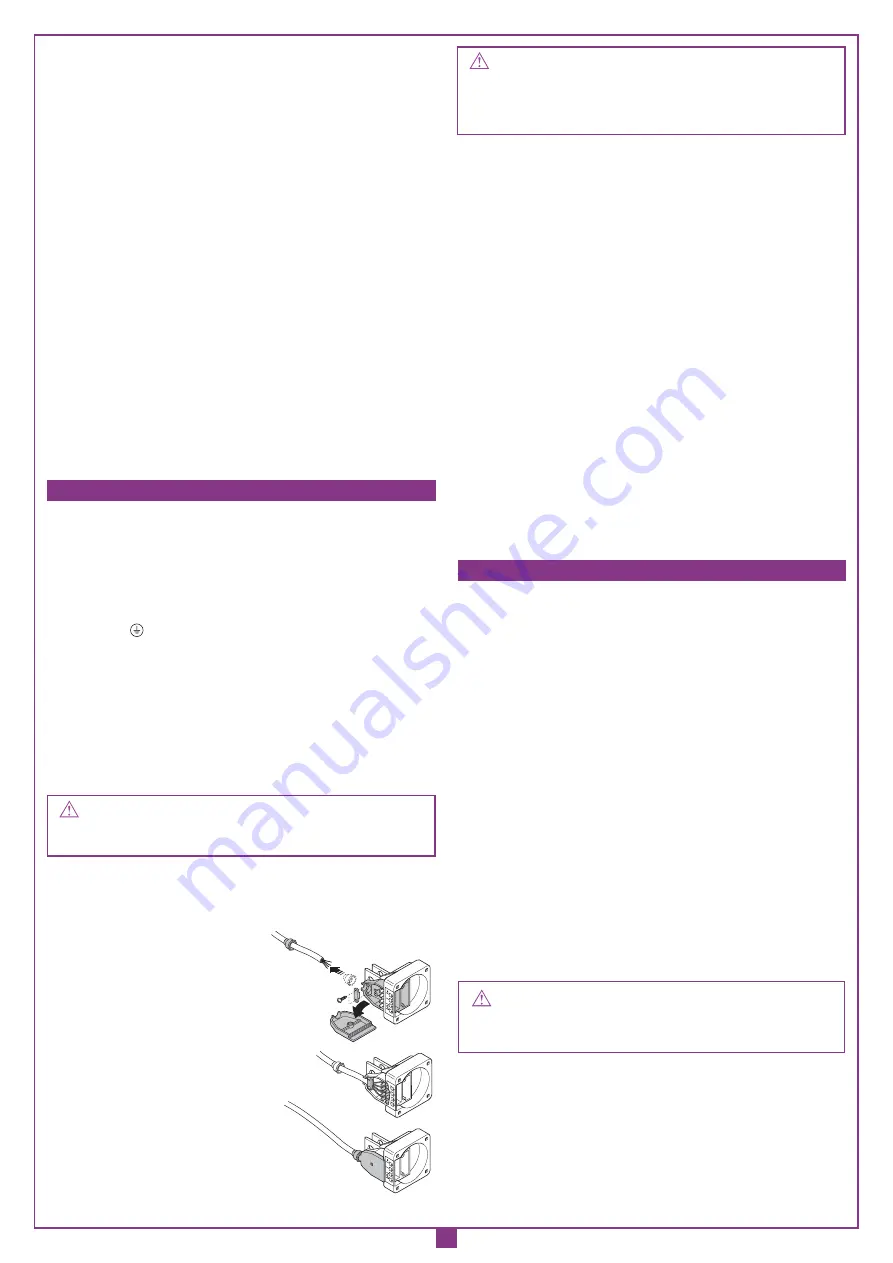
Power cable rubber sealing cap

1) Fit the sealing cap on to the power 

cable and slide it down enough to 

allow you to connect the cable to the 

terminal board. 

2) Fasten down the cable using the cable 

clamp. 

3) Close the cover and slide the sealing 

cap up over the cable entry opening.  

This action is extremely important and will

guarantee a protection grade of IP44.  

  ELECTRICAL CONNECTION 

(

fi

 g. 19-21 page 9-11)

  MANUAL RELEASE MECHANISM 

(

fi

 g.12, page 6) 

Summary of Contents for 200/BL202

Page 1: ...nze importanti Pag 12 Istruzioni per l uso Pag 12 Istruzione per l installazione Pag 13 Collegamento elettrico Pag 14 Sblocco manuale Pag 14 Caratteristiche tecniche Pag 28 OPGELET Lees deze handleidi...

Page 2: ...ue int rieure 3 Cellule photo lectrique ext rieure 4 Bo te de d rivation 5 Clignoteur 6 Armoire lectronique 7 S lecteur cl 8 Interrupteur omnipolaire avec ouverture des contacts d au moins 3mm 9 Serru...

Page 3: ...0 BL452 200 BL352 e 200 BL452 sono privi di sblocco 9 200 BL352 and 200 BL452 do not feature manual release 9 200 BL352 et 200 BL452 sont d pourvus de dispositif de d verrouillage 9 200 BL352 und 200...

Page 4: ...280 mm TRAVEL DISTANCE A 280 mm COURSE UTILE A 280 mm BRUIKBARE KOERS A 280 mm CORSA UTILE C 350 mm TRAVEL DISTANCE C 350 mm COURSE UTILE C 350 mm ARBEITSHUB C 350 mm BRUIKBARE KOERS C 350 mm CORSA U...

Page 5: ...38 5 17 7 20 8 110 180 210 0 80 90 20 30 6 35 39 9 45 7 24 4 28 110 200 180 0 80 90 20 33 38 8 33 38 8 16 19 110 X Spessore da aggiungere a cura dell installatore X Spacer to be added by the installer...

Page 6: ...UALE MANUAL RELEASE D VERROUILLAGE MANUEL MANUELLE ENTRIEGELUNG MANULE ONTGRENDELING ESEMPIO D INSTALLAZIONE INSTALLATION EXAMPLE EXEMPLE D INSTALLATION INSTALLATIONSART INSTALLATIEVOORBEELD 2 1 3 11...

Page 7: ...T BRACKET TO THE GATE FIXATION DE LA PATTE ANT RIEURE AU PORTAIL ANBRINGUNG HALTEB GEL VORNE AM TOR MONTAGE MOGELIJKHEDEN OP HET HEKKEN FISSAGGIO STAFFAANTERIORE A CANCELLO FITTING THE FRONT BRACKET T...

Page 8: ...AANTERIOREREGOLABILE OPZIONALE FITTINGTHEADJUSTABLEFRONTBRACKET OPTIONAL PATTEANT RIEURER GLABLE EN OPTION VORNER EINSTELLBARER HALTEB GEL EXTRA MONTAGE OPTIONEELAFREGEL SYSTEEM HEKKEN 94 min 131 max...

Page 9: ..._1 NC NC COMUNE FCC_2 FCA_2 NC NC COMUNE NA C OUT CH2 LS 24V3W ELS 12V15W OUT 24V NA NA NA NA LC 110 230V LP 110 230V M2 CHIUSURA COMUNE APERTURA C M1 CHIUSURA COMUNE APERTURA N F 41 40 39 SEL 24V PON...

Page 10: ...ATOR LAMP 24Vac ELS ELECTRIC LOCKING DEVICE 12Vac NO NORMALLY OPEN CONTACT NC NORMALLY CLOSED CONTACT C NO NC 1 BRIDGE BSP NC FUSE 5A 230V 10A 110V C1 TORQUE LIMITER Max 110 Vac A 100 Vac B 90 Vac C 8...

Page 11: ...A OPENING TRAVEL LIMIT bridge if unused FTC_S STOP PHOTOCELL bridge if unused FTC_I INVERTING PHOTOCELL bridge if unused LP FLASHING WARNING LIGHTS 24Vac LS INDICATOR LAMP 24Vac ELS ELECTRIC LOCKING D...

Page 12: ...essere sufficientemente lontana dalla strada in modo da non costituire pericolo per la circolazione 2 L operatore deve essere installato all interno della propriet ed il cancello non deve aprirsi vers...

Page 13: ...ig 2 pag 3 Sistemare il carter di protezione fissando le 4 viti posizionate sul riduttore pos 2 fig 2 e fissare il tappo in plastica pos 4 fig 2 Sempre a motore sbloccato portare l anta in apertura fi...

Page 14: ...l attuatore part 4 fig 3 fino ad arrivare a 15mm dal completamento della corsa in chiusura Fissare con l apposito perno 1 l attuatore alla staffa di coda 6 fig 3 pag 3 Portare l attuatore nella normal...

Page 15: ...NING KEEP CLEAR CHILDREN OR PETS MUST NOT BE ALLOWED TO PLAY ON OR NEAR THE INSTALLATION WARNING These instructions are aimed at professionally qualified INSTALL ERS OF ELECTRICAL EQUIPMENT and must r...

Page 16: ...then fasten the front bracket onto the reinforcing plate Insert the arm in the front bracket 6 insert the retaining pin 7 and fasten down using the supplied C clips fig 2 pag 3 Install the protective...

Page 17: ...plied screws fig 2 pag 3 Rotate the never ending screw part 4 fig 3 until it reaches 15mm from the end of the closing direction travel distance Fix the arm to the rear mooring bracket 6 using the reta...

Page 18: ...TRE AUX ENFANTS ET AUX ANIMAUX DOMESTIQUES DE STATIONNER DANS LE RAYON D ACTION DU PORTAIL ATTENTION LIRE ATTENTIVEMENT LES CONSIGNES SUIVANTES AVANT DE PROC DER L INSTALLATION PR TER GRANDE ATTENTION...

Page 19: ...s fig 2 page 3 Proc der la mise en place du carter de protection en vissant les 4 vis qui se trouvent sur le r ducteur pos 2 fig 2 et fixer le capot d extr mit en plastique pos 4 fig 2 Toujours avec m...

Page 20: ...oupe pr vu cet effet 3 Remettre le couvercle sa place et appliquer le capuchon de telle fa on couvrir l entr e du c ble Ceci est indispensable pour garantir un indice de protection IP44 IMPORTANT Cons...

Page 21: ...rauchsfrequenz muss sich nach den verschiedenen Modellen richten siehe technische Eigenschaften Seite 28 WICHTIGE HINWEISE WICHTIGE HINWEISE WICHTIGE HINWEISE EINIGE BETRACHTUNGEN ZUR SICHERHEIT AUTOM...

Page 22: ...chen Schrauben 2 bis zum Anschlag anziehen anbringen und die kappe aus Kunststoffma Vor der Installation ist zu berpr fen dass die zu automatisierende Einrichtung in ihren festen und beweglichen Teile...

Page 23: ...i ber den Kabeleinlass st l pen Dies ist zur Gew hrleistung des Schutzgrades IP44 der Verkabelung unerl sslich ELEKTRISCHER ANSCHLUSS Abb 19 21 S 9 11 WICHTIG Der Getriebemotor besitzt keinen Drehmome...

Page 24: ...antwoordelijkheid van de installateur om ervoor te zorgen dat volgende publieke veiligheidsmaatregels in acht worden genomen 1 Zorg ervoor dat de poort ver genoeg van de weg staat om verkeersproblemen...

Page 25: ...Monteer de motor in de motorsteunen en maak deze vast met de pinnen 1 en 7 en de bijhorende clips Schuif de aluminium kap over de piston maak deze vast met de 4 vijzen en breng de plastiek kap aan op...

Page 26: ...E KRACHTINSTELLING VAN DE MOTOR op de besturingskast HetisaangeradeneenCardinbesturingskastmetkrachtregelingtegebruiken om de motoren te sturen De Cardin besturingskasten optimaliseren de werking van...

Page 27: ...Standards and Certification Guide l installation Le guide l installation a t r dig par Cardin Elettronica dans l objectif de faciliter l installateur l application des dispositions des directives mac...

Page 28: ...44 44 Dimensione anta max m 2 2 4 1 8 3 3 5 4 5 Peso max anta Kg 150 150 150 300 300 Power supply V 230 230 230 230 230 Frequency Hz 50 50 50 50 50 Electrical input A 1 79 1 79 1 79 1 3 1 4 Power inpu...

Reviews: