Chapter 8
8-16
2827
2828
2829
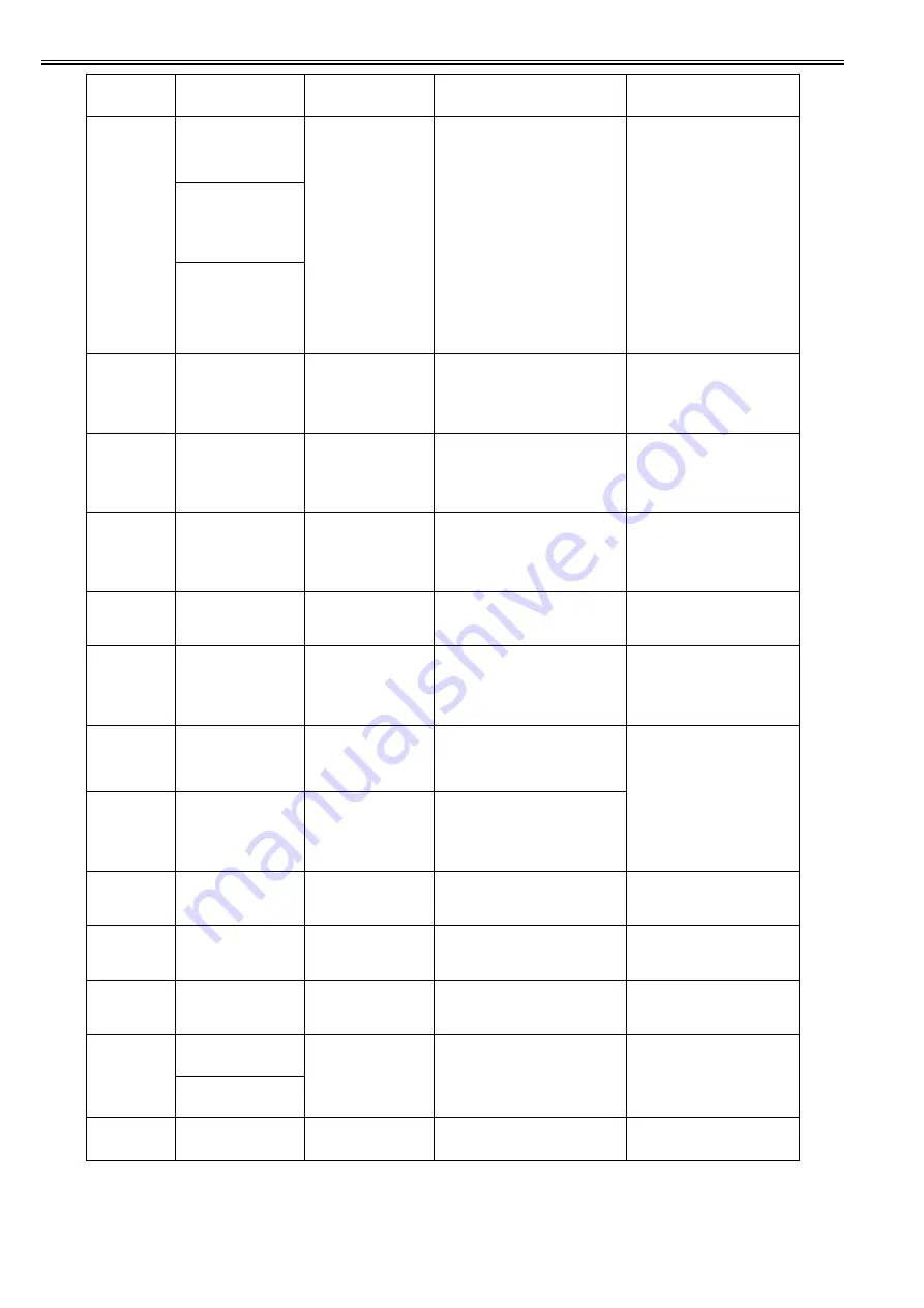
Execute printhead
cleaning. If this
message is still
displayed, replace
Printhead.
Printhead non-discharge error
(Replace printhead/ continued printing not
allowed)
At start of printing the number of non-
ejecting nozzles is more than 320 per color
(1 chip).
2827: Both L and R, or single printhead
model
2828: R printhead
2829: L printhead
* For the detailed head non-ejection errors,
see section 280C.
(If Setting of SERVICE MODE >
SETTING >HEAD WARNING is off, the
error code is 280E.)
1. Execute cleaning.
2. Replace printhead.
Execute printhead
cleaning. If this
message is still
displayed, replace
Printhead.
[Stop: Stop Printing
Execute printhead
cleaning. If this
message is still
displayed, replace
printhead .
Printing stopped.
[OK]
282A
CR MOTOR TUNING
ERROR :PRESS OK
Carriage motor identification processing
(rotation adjustment) failed (for Service
mode)
Error is cleared by OK button.
1. Check installation of carriage or
carriage belt.
2. Clean the carriage main rail (Do not
oil it.)
3. Replace the carriage motor.
282B
CR VIBRATION
ERROR :PRESS OK
When processing carriage motor
identification (rotation adjustment),
carriage vibration has been detected (for
Service mode).
Error is cleared by OK button.
1. Check installation of carriage or
carriage belt.
2. Clean the carriage main rail (Do not
oil it.)
3. Replace the carriage motor.
282D
Left printhead
error.
Turn off printer,
wait, then
turn on again.
Printhead error detected (L head only).
Displayed when an abnormal temperature
rise of printhead has been detected to
prompt you to restart.
After restarting, replace the printhead
L.
282E
!Printhead error
Turn off printer,
wait, then
turn on again.
Temperature rising detected by particular
ink pre-injection before printing was
judged abnormal.
1. Replace the printhead.
2. Replace the main controller PCB.
2830
Left printhead
error.
Open top cover and
replace the left
printhead.
Printhead error detected (L head only).
Displayed when restarting after detection
of error 282D to prompt you to replace
printhead L.
Replace the printhead L.
2832
Hardware error
03130031-2832
Turn off printer,
wait, then
turn on again.
VHT leak detection error of right printhead
or of a single printhead, in case of VHT
exceeds rated value or falls below the rated
value.
iPF6300/6400 Series
iPF8300/8400/9400
Series
Replace right or left
printhead.
2833
Hardware error
03130031-2833
Turn off printer,
wait, then
turn on again.
VHT leak detection error of left printhead,
in case of VHT exceeds rated value or falls
below the rated value.
2834
!Unknown printhead. Open
top cover and re-install
printhead.
Printhead contact failure is detected after
the
printhead installation.
1. Remove and reinstall the printhead.
2. Replace the printhead.
3. Replace the carriage unit.
4. Replace the main controller PCB.
2835
!Cannot recognize print
head R.
Open the top cover and re-
insert the printhead R.
Printhead contact failure is detected after
the
printhead installation.
1. Remove and reinstall the printhead.
2. Replace the printhead.
3. Replace the carriage unit.
4. Replace the main controller PCB.
2836
!Cannot recognize print
head L.
Open the top cover and re-
insert the printhead L.
Printhead contact failure is detected after
the
printhead installation.
1. Remove and reinstall the printhead.
2. Replace the printhead.
3. Replace the carriage unit.
4. Replace the main controller PCB.
2901
Mail box
nearly full.
Delete unwanted data
The available size of the permanent area of
the hard disk space has fallen to less than 1
GB.
Reorganize data.
The mail box is
nearly full. Delete
unwanted jobs.
2902
Mail box full.
Now printing
without saving data.
The hard disk has run out of free space,
disabling copy printing or error recovery.
Reorganize data.
Code
(last 4 digits)
Panel display
(Large LCD)
Panel display
(Small LCD)
Explanation/Detection sequence
Remedial Action
Summary of Contents for iPF8400S Series
Page 1: ...Feb 27 2017 Service Manual iPF8000 series iPF8400S ...
Page 2: ......
Page 6: ......
Page 11: ...Chapter 1 PRODUCT DESCRIPTION ...
Page 12: ......
Page 14: ......
Page 63: ...Chapter 2 TECHNICAL REFERENCE ...
Page 64: ......
Page 106: ......
Page 107: ...Chapter 3 INSTALLATION ...
Page 108: ......
Page 110: ......
Page 123: ...Chapter 3 3 13 F 3 22 6 FAN UNIT A ...
Page 125: ...Chapter 3 3 15 ...
Page 126: ......
Page 127: ...Chapter 4 DISASSEMBLY REASSEMBLY ...
Page 128: ......
Page 130: ......
Page 167: ...Chapter 4 4 37 ...
Page 168: ......
Page 169: ...Chapter 5 MAINTENANCE ...
Page 170: ......
Page 172: ......
Page 177: ...Chapter 6 TROUBLESHOOTING ...
Page 178: ......
Page 180: ......
Page 215: ...Chapter 7 SERVICE MODE ...
Page 216: ......
Page 218: ......
Page 272: ...Chapter 7 7 54 ...
Page 273: ...Chapter 8 ERROR CODE ...
Page 274: ......
Page 276: ......
Page 311: ...Feb 27 2017 ...
Page 312: ......


