background image

1

1

1-35

1-35

Initial Setup > Adjustments/Settings > Adjustment/Maintenance Menu screen > Output Test Page

Initial Setup > Adjustments/Settings > Adjustment/Maintenance Menu screen > Output Test Page


Job Type to Apply

When performing [Auto Correct Color Tone], corrections of color tone are applied to copy/
print jobs. Corrections can be applied separately for copy job or print job. If you do not want 
to change the color tone of either copy or print job, set [Off] for the job type you do not want to 
apply to in [Job Type to Apply To].

F-1-64


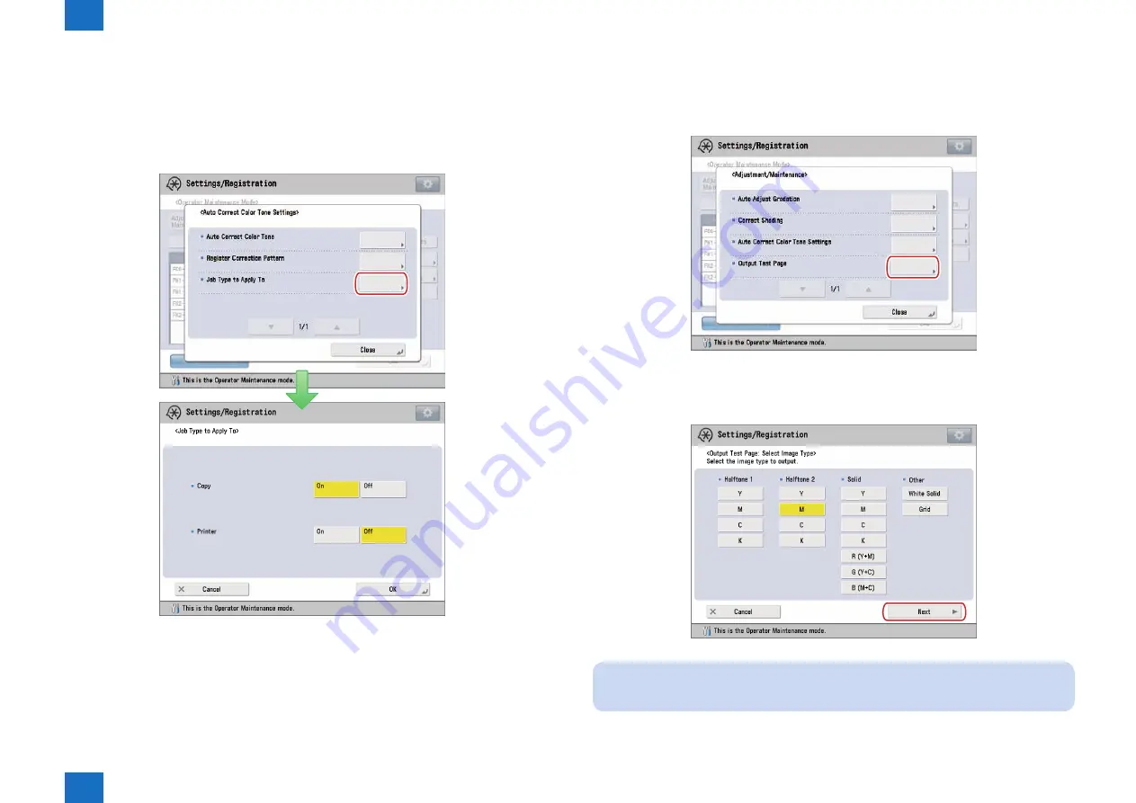
Output Test Page

Execute the output test page with the following procedure.

1) Press [Output Test Page] on Adjustment/Maintenance Menu screen.

-> Output Test Page: Image Type Selection screen is displayed.

2) Select the image type to be output, and press [Next].

NOTE:

As for the setting items for the image type, multiple selections are possible.

-> Output Test Page: Paper Selection screen is displayed.

F-1-65

F-1-66

Summary of Contents for imagePRESS C800 Series

Page 1: ...2 1 imagePRESS C800 C700 C60 Series Operator Maintenance Manual Revision 1 February 23 2015 Initial Setup Procedure of Replacement Cleaning...

Page 2: ...ation as the need arises In the event of major changes in the contents of this manual over a long or short period Canon will issue a new edition of this manual The following paragraph does not apply t...

Page 3: ...on of the electric signal The expression turn on the power means flipping on the power switch closing the front door and closing the delivery unit door which results in supplying the machine with powe...

Page 4: ...aring the Counter of the Fixing Assembly 1 12 Procedure for Clearing the Counter of the Secondary Transfer Outer Roller Fixing Refresh Roller 1 14 Replacement Cleaning Mode 1 15 Moving to Replacement...

Page 5: ...1 1 Initial Setup Initial Setup Basic Operation Adjustments Settings...

Page 6: ...below shows the relation between Operator Maintenance mode and Replacement Cleaning mode Replacement Cleaning Mode Operator Maintenance Mode Press Adjustment Maintenance Operator Maintenance Operator...

Page 7: ...nce mode 1 Press Settings Registration Adjustment Maintenance Operator Maintenance NOTE When the Operator Maintenance is not displayed contact the service representative 2 Press Operator Maintenance M...

Page 8: ...erator maintenance mode is terminated to return to Operator Maintenance Adjustment Maintenance screen F 1 6 F 1 7 Auto timeout Notification When no operation is made for certain duration in Operator M...

Page 9: ...nce Log Maintenance Log List Screen in Operator Maintenance Mode page 1 7 Replaceable Parts Replaceable Parts List Screen in Operator Maintenance Mode page 1 8 Cleanable Parts Cleanable Parts List Scr...

Page 10: ...nance mode so any changes made during login are not reflected here F 1 10 Display Items Contents Item No 8 digits characters and or numbers format XXX XXXX Replacement Cleaning Icons Replacement icon...

Page 11: ...XXX Replacement Cleaning Icons Replacement icon Cleaning icon Maintenance Max 34 single byte characters overflow will be rounded Date of Counter Cleared Year Month Day For Japan Month Day Year For U S...

Page 12: ...d or numbers format XXX XXXX Replacement Icon Maintenance Max 34 single byte characters overflow will be rounded Wear Status 0 to 999 Count 8 digit numbers Recommended Value 8 digit numbers Control Ke...

Page 13: ...y format Cleaning Icon Maintenance Max 34 single byte characters overflow will be rounded Wear Status 0 to 999 Count 8 digit numbers Recommended Value 8 digit numbers Control Keys Names of Key Functio...

Page 14: ...creen for the cleanable parts F 1 14 F 1 15 Display Displayed items are in common on both replacement and cleanable detailed display Items Contents ID Alphanumeric 6 digit Only the Fixing Assembly is...

Page 15: ...Operation screen of Fixing Assembly may be displayed The Fixing Assembly ID is displayed in the Counter Operation screen F 1 16 Control key Items Contents ID Up to 10 IDs can be displayed IDs are regi...

Page 16: ...and press the Details The screen showing the details of the selected Fixing Assembly will appear NOTE This information shows the state of the Fixing Assembly registered by the service technician F 1...

Page 17: ...perform step 4 3 Select the ID of the Fixing Assembly you wrote down in step 1 and press OK NOTE If the ID of the Fixing Assembly you wrote down in step 1 is not displayed select No ID In addition let...

Page 18: ...rm 1 1 When clearing the counter of the Fixing Refresh Roller perform 1 2 1 1 In the Warning or Replaceable Parts screen select Secondary Transfer Outer Roller and press Counter Operation 1 2 In the W...

Page 19: ...jobs or PDL jobs are executed in the control panel End the jobs to enable To Rplcmt Cleaning If To Rplcmt Cleaning is pressed immediately after pressing Print List wait time of approx 2 minutes is re...

Page 20: ...finished clear the counters exit Replacement Cleaning mode and then return to Operator Maintenance mode For clear the counter refer to Clearing the Counter page 1 12 1 Press End Rplcmt Cleaning on rep...

Page 21: ...maintenance operation screen 1 In operator maintenance basic screen press Adjustment Maintenance Adjustment maintenance screen is displayed F 1 34 F 1 35 2 In adjustment maintenance menu screen selec...

Page 22: ...complete the machine automatically corrects the irregularities CAUTION Make sure to perform this function in the stable room environment i e temperature and humidity The color may become unstable due...

Page 23: ...nt Use the Duplex Color Image Reader Unit H1 In this procedure you need to scan the printed test pages 3 times You need to place test pages on the platen glass for scanning but it takes shorter time f...

Page 24: ...When Using the Auto Gradation Sensor A1 Do Not Use Scanner To perform this procedure you must log in to this machine as an administrator F 1 39 NOTE Confirm that the following size and type of paper...

Page 25: ...ets 2 1 sheet 2 sheets 2 sheets 5 sheets 3 1 sheet 3 sheets 3 sheets 7 sheets 4 1 sheet 4 sheets 4 sheets 9 sheets 5 1 sheet 5 sheets 5 sheets 11 sheets Number of sheets to output for test page when u...

Page 26: ...ng the top back edge of the platen glass NOTE Make sure to place the last output if the multiple second test pages are output To perform more precise full adjustment you can increase the number of she...

Page 27: ...re equivalent to the Hammermill Color Copy Digital 28lb 105 g m2 as paper to adjust Accurate recalibrations of the gradation density and color settings of the machine may not be made if you register a...

Page 28: ...effective adjustments select the correct paper type 6 Press Start Printing First test page is output NOTE If you are using the Auto Gradation Sensor A1 steps 7 to 8 are not necessary Proceed to step 9...

Page 29: ...on you must log in to this machine as an administrator 1 In Adjustment Maintenance menu screen press Auto Adjust Gradation Automatic adjustment gradation screen is displayed F 1 47 2 Press Select Pape...

Page 30: ...administrator NOTE When you set By Paper Type Group for Adjustment Level you can select the paper type and make effective adjustments according to the paper type that you select from Thin 1 Plain Heav...

Page 31: ...perform automatic gradation adjustment but cannot adjust gradation density or color correctly or scanned error message appears for the test page set Initialize When Using Full Adjust to On and then p...

Page 32: ...the output results of the test page and adjusting the density manually Select this mode to correct uneven densities if the densitometer is unavailable or the densitometer correction is unsatisfactory...

Page 33: ...rom 0 to 8 are shown on the test page make sure to gauge and enter the density values for all imprinted marks If the marks 0 and 8 are not shown on the test page gauge and enter the density values for...

Page 34: ...ance menu screen press Correct Shading Shading correction screen is displayed F 1 55 2 Press Visual Correction Output Test Page Start Printing Test page 2 with marks from 7 to 6 is output NOTE The mar...

Page 35: ...g a test page and reading it with the optional Duplex Color Image Reader Unit H1 CAUTION Make sure to perform this function in the stable room environment i e temperature and humidity The color may be...

Page 36: ...ings Automatic color tone correction screen is displayed 2 Press Auto Correct Color Tone A screen for checking whether or not auto gradation adjustment full adjustment has been performed will appear F...

Page 37: ...E The name of the paper is subject to change without notice For more information contact with service technician 6 Press Start Printing Test page is output 7 Place the test page face down on the plate...

Page 38: ...LTR Basis Weight Finish Whiteness Thin 1 Plain 1 Plain 2 or Heavy 1 to Heavy 6 Uncoated that has the same whiteness of the Hammermill Color Copy Digital 28lb 105 g m2 Custom paper type whose basis wei...

Page 39: ...nt job If you do not want to change the color tone of either copy or print job set Off for the job type you do not want to apply to in Job Type to Apply To F 1 64 Output Test Page Execute the output t...

Page 40: ...3 mm Plain paper is the recommended paper type The duplexing mode is not available for the test print When the test print completes normally it automatically returns to Adjustment Maintenance Menu scr...

Page 41: ...u screen select the item intended to change 1 Press Management Settings on Operator Maintenance Basic screen Management Setting Menu screen is displayed 2 On Management Setting Menu screen select the...

Page 42: ...g Menu screen Change Password screen is displayed 2 Enter the password NOTE Only 7 digit numbers can be set for the password 3 Press Confirm and reenter the password for confirmation 4 Press OK F 1 70...

Page 43: ...s 3 Press Yes F 1 74 Settings of Auto Timeout Conditions The auto timeout time of the Operator Maintenance mode can be changed Assignable values 0 Off 5 mins 10 mins 20 mins 30 mins 1 hour 90 mins 2 h...

Page 44: ...ed If Display Log needs to be displayed for the use of this function contact a servicing person Display Log is not displayed in the Replacement Cleaning mode therefore this function cannot be used F 1...

Page 45: ...placement Cleaning mode 1 Press JAM on the log display menu screen The JAM screen is displayed F 1 79 F 1 80 2 Confirm the log of jam JAM 3 After confirming the log press OK The contents of the displa...

Page 46: ...ed in the Replacement Cleaning mode 1 Press ERR on the log display menu screen The ERR screen is displayed F 1 81 F 1 82 2 Confirm the log of error ERR 3 After confirming the log press OK The contents...

Page 47: ...ent Cleaning mode 1 Press ALARM 2 on the log display menu screen The ALARM 2 screen is displayed F 1 83 F 1 84 2 Confirm the log of alarm ALARM 2 3 After confirming the log press OK The contents of th...

Page 48: ...2 2 Procedure of Replacement Cleaning Procedure of Replacement Cleaning List of Operator Replaceable Cleanable Parts Transfer area Fixing area Cleaning...

Page 49: ...SS C800 image PRESS C700 image PRESS C600 image PRESS C60 Auto Adjust Gradation Correct Shading Auto Correct Color Tone Settings Output Test Page Transfer area Secondary Transfer Outer Roller FC0 9786...

Page 50: ...Transfer area Replacing the Secondary Transfer Unit Replacement procedure Transfer area Replacing the Secondary Transfer Unit Replacement procedure CAUTION Be sure not to touch the surface A of the S...

Page 51: ...Springs 1 at both sides of the rail to release the locks and further pull out the Fixing Feed Unit 2 until it stops 1 1 2 F 2 4 CAUTION Do not release the locks of the 2 Release Springs 3 at the rear...

Page 52: ...the Secondary Transfer Unit Replacement procedure 4 Remove the Fixing Feed Sub Cover 1 1 Screw 2 to loosen 2 Hooks 3 1x 1 2 3 3 NOTE How to install the Fixing Feed Sub Cover Put the A part of the Fix...

Page 53: ...TB may be damaged How to release the pressure applied on the Secondary Transfer Outer Roller The pressure on the Secondary Transfer Outer Roller 3 can be released by turning the gear 1 and changing th...

Page 54: ...leaning Fixing area Replacing the Fixing Assembly Replacement procedure Fixing area Replacing the Fixing Assembly Replacement procedure CAUTION Because the Fixing Assembly 1 is hot be sure to replace...

Page 55: ...t both sides of the rail to release the locks and further pull out the Fixing Feed Unit 2 until it stops 1 1 2 F 2 13 CAUTION Do not release the locks of the 2 Release Springs 3 at the rear on the rai...

Page 56: ...placing the Fixing Assembly Replacement procedure 4 Remove the Fixing Upper Cover 1 1 Screw 2 2 Hooks 3 1x 1 2 3 F 2 15 CAUTION Be sure to check that the 2 hooks 3 are hooked when installing the Fixin...

Page 57: ...Replacing the Fixing Assembly Replacement procedure Procedure of Replacement Cleaning Fixing area Replacing the Fixing Assembly Replacement procedure 5 Disconnect the 4 connectors 1 1 1 4x F 2 18 6 Lo...

Page 58: ...ide of the Fixing Assembly 2 and place the connector 3 on the Feed Guide 4 8 Lift the rear side and remove the Fixing Assembly 2 while keeping the unit in a horizontal position 1 2 2 4 3 F 2 20 CAUTIO...

Page 59: ...ally and align the 2 holes A with the 2 Positioning Protrusions B of the Fixing Feed Unit to install the assembly 1 A B A B F 2 22 9 From the Adjustment Maintenance menu execute Automatic Gradation Ad...

Page 60: ...ment Cleaning Cleaning Cleaning the Fixing Refresh Roller Cleaning Procedure Cleaning Cleaning the Fixing Refresh Roller Cleaning Procedure CAUTION Because the Fixing Assembly 1 is hot be sure to clea...

Page 61: ...t both sides of the rail to release the locks and further pull out the Fixing Feed Unit 2 until it stops 1 1 2 F 2 25 CAUTION Do not release the locks of the 2 Release Springs 3 at the rear on the rai...

Page 62: ...ning the Fixing Refresh Roller Cleaning Procedure 4 Remove the Fixing Upper Cover 1 1 Screw 2 2 Hooks 3 1x 1 2 3 F 2 27 CAUTION Be sure to check that the 2 hooks 3 are hooked when installing the Fixin...

Page 63: ...UTION Do not touch the surface A of the Fixing Belt and the surface B of the Pressure Belt A B F 2 31 F 2 30 6 By rotating the Fixing Refresh Roller while holding its edge A the area 1 cm from the two...

Page 64: ...er Cleaning Procedure 7 From the Adjustment Maintenance menu execute Automatic Gradation Adjustment Refer to page 1 18 8 From the Adjustment Maintenance menu execute Shading Correction Refer to page 1...

Reviews: