Canon imageCLASS X LBP1238 Service Manual Download Page 13

 Notes When Handling a Lithium Battery

Dispose of used batteries according to the instructions.
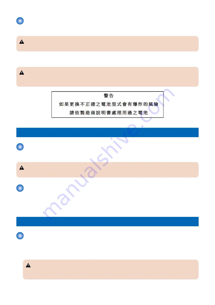
 CAUTION:

Risk of explosion if battery is replaced by an incorrect type.

The following warnings are given to comply with Safety Principles (EN60950-1).

 CAUTION:

Wenn mit dem falschen Typ ausgewechselt, besteht Explosionsgefahr.
Gebrauchte Batterien gemäß der Anleitung beseitigen.

Toner Safety

 About Toner

Toner is a non-toxic material composed of plastic and small amount of pigment.

 CAUTION:

Never throw toner in flames to avoid explosion.

 Handling Adhered Toner

• Use dry tissue paper to wipe off toner adhered to skin or clothes and wash in water.
• Never use warm water for cleaning up toner to prevent toner particles from being gelated to soak into fibers permanently.
• Toner particles are reactive with vinyl polymers. Avoid contacting these materials.

Notes on works

 Points to Note Before Servicing

• At servicing, be sure to turn OFF the power source according to the specified steps and disconnect the power plug.
• Be sure to disconnect the power plug on a regular basis and remove dust and dirt accumulated around the outlet with dry

cloth.

 CAUTION:

Leaving the power plug connected for a long time in an environment having a lot of dust, moisture, or oily smoke will
cause a fire. (Because dust accumulated in the surrounding area will absorb moisture and cause an insulation failure)

Safety Precautions

3

Summary of Contents for imageCLASS X LBP1238

Page 1: ...SERVICE MANUAL imageCLASS X LBP1238 II Canon November 24 2021 Rev 3 COPYRIGHT 2021 CANON INC CANON imageCLASS X LBP1238 II Rev 3 PRINTED IN U S A...

Page 2: ...iPod touch Mac OS X and Safari are trademarks of Apple Inc Microsoft Windows Windows Vista Windows Server Internet Explorer Microsoft Edge Excel and PowerPoint are either registered trademarks or trad...

Page 3: ...1x Loosen the screw 1x Install the screw 1x Tighten the screw Cleaning is needed Measurement is needed The following rules apply throughout this Service Manual 1 Each chapter contains sections explai...

Page 4: ...ssors used in the machines are not discussed they are explained in terms of from sensors to the input of the DC controller PCB and from the output of the DC controller PCB to the loads The description...

Page 5: ...5 Product Lineup 6 Host Machine 6 Options 6 Features 8 Specifications 9 Product Specifications 9 Paper Type 10 Paper Size 10 Parts Name 12 External Cover 12 Cross Section View 15 Control Panel 16 2 T...

Page 6: ...ry Tray Full Detection 42 Jam Detection 42 3 Technical Explanation System 44 Overview of System Management 45 Version Upgrade 46 Function Overview 46 Version Upgrade Using UST 47 Version Upgrade via I...

Page 7: ...CB 105 Removing the Main Controller Unit 106 Removing the DC Controller PCB Cover 107 Remove the DC Controller PCB 108 Removing the High Voltage Power Supply PCB 108 Removing the Low Voltage Power Sup...

Page 8: ...in fixing power supply drive circuit 148 E012 0000 Error in startup of Main Motor 148 E012 0001 Main Motor rotation error 148 E015 0000 Main Motor error 149 E020 0000 Error in Color Displacement Dens...

Page 9: ...error 152 E766 8000 Firmware error 152 E766 9000 Scanner power state error 152 E804 0004 Controller FAN Error 152 E806 0000 Main Fan error 152 E840 0000 Pressure release mechanism error 153 E996 0071...

Page 10: ...Backup Data List 202 Soft counter specifications 204 List of Items Which Can Be Imported 205 Service Mode Settings 205 Contents vi...

Page 11: ...Safety Precautions Laser 2 Power Supply Lithium Battery 2 Toner Safety 3 Notes on works 3...

Page 12: ...canner unit Dieses Ger t ist der Klasse 1 der Laserprodukte zugeordnet Allerdings enth lt die Laserscannereinheit eine Laserstrahlquelle der Klasse 3B die Augensch den verursachen kann wenn man in die...

Page 13: ...ed to skin or clothes and wash in water Never use warm water for cleaning up toner to prevent toner particles from being gelated to soak into fibers permanently Toner particles are reactive with vinyl...

Page 14: ...avoid any potential dangers during assembling disassembling works 2 If not specially instructed reverse the order of disassembly to reinstall 3 Ensure to use the right screw type length diameter etc...

Page 15: ...Product Overview 1 Product Lineup 6 Features 8 Specifications 9 Parts Name 12...

Page 16: ...trol Panel 5 inch Color Touch Panel 5 lined LCD Numeric keys NFC MEAP Wired LAN Yes Yes Wireless LAN Yes Yes PDL LBP1238 II 1238P II 1238Pr II UFR II Yes PS Yes PCL Yes Options Name Remark Cassette Fe...

Page 17: ...Name Remark MiCARD Attachment Kit B1 IC Card Reader sales company s option is required 1 Product Overview 7...

Page 18: ...m upgrade model of LBP1238 series which is the current model Usability improvement Wifi setting improvement Added linkage with cloud storage Enhancement of security Support for TLS1 3 Support for HTTP...

Page 19: ...sided printing 38 0 ppm A4 40 0 ppm LTR At 2 sided printing 31 9 ppm A4 33 3 ppm LTR Warm up time 3 14 sec or less Recovery time 4 Approx 4 sec or less First print time Multi purpose Tray pickup Appro...

Page 20: ...r is turned ON to when the basic screen appears This may vary depending on the usage conditions and environment of this machine 4 The time for recovery from sleep to standby 5 The actual stack capacit...

Page 21: ...mm x 341 0 mm Yes Yes Yes G LTR 203 2 mm x 266 7 mm Yes Yes G LGL 203 2 mm x 330 2 mm Yes Yes FLSC 215 9 mm x 330 2 mm Yes Yes Yes AFLS 206 0 mm x 337 0 mm Yes Yes Indian LGL 215 0 mm x 345 0 mm Yes...

Page 22: ...II 4 5 6 7 8 2 1 10 3 2 11 9 10 No Name No Name 1 USB port 7 Pickup Cassette 2 Handle for carrying 8 Delivery Tray 3 Ventilation hole 9 Front Cover Open Button 4 Control Panel 10 Power Switch 5 Front...

Page 23: ...0 1 9 No Name No Name 1 Control Panel 6 Pickup Cassette 2 Handle for carrying 7 Delivery Tray 3 Ventilation hole 8 Power Switch 4 Front Cover 9 Front Cover Open Button 5 Delivery Stopper 10 Multi purp...

Page 24: ...the Machine LBP1238 II 1238P II 3 4 5 6 1 2 1238Pr II 3 4 5 6 1 2 No Name No Name 1 Rear Cover 4 USB port for USB device 2 Rating name plate label 5 USB port for PC 3 Power Socket 6 LAN Port 1 Produc...

Page 25: ...ler 3 Delivery Roller 14 Cassette Separation Roller 4 Pressure Roller 15 Cassette 5 Fixing Film 16 Cassette Pickup Roller 6 Fixing Assembly 17 Duplex Re pickup Roller 7 Laser Scanner Unit 18 Registrat...

Page 26: ...Control Panel LBP1238 II 1238P II 3 2 4 5 6 7 1 No Name No Name 1 Display 5 Error Lamp 2 Volume key 6 Home key 3 Energy Saver Key 7 Stop key 4 Data Lamp 1 Product Overview 16...

Page 27: ...ication key 2 Home key 11 Clear key 3 Back key 12 Stop key 4 Numeric keys 0 to 9 13 Symbol key 5 Kana Alphabetic Numeric key 14 Utility key key 6 Data Lamp 15 Job key key 7 Error Lamp 16 Setup key key...

Page 28: ...Technical Explanation Device 2 Basic Configuration 19 Controller System 20 Laser Exposure System 26 Image Formation System 28 Fixing System 33 Pickup Feed System 36...

Page 29: ...ystem Pickup Feed System Fixing System Image Formation System Laser Exposure System Drum Laser scanner Duplex Feed System Main controller DC controller Controller System Laser beam Paper flow simplex...

Page 30: ...Controller PCB Printer control laser control high voltage control various I O control and retaining setting values Main Controller PCB CAUTION The number of connectors varies depending on the model J9...

Page 31: ...CB 5 lines J927 Control Panel PCB I F touch panel J916 1 NCU PCB I F 1 Models with FAX only DC Controller PCB Description J5 J4 J10 J2 J9 J8 J7 J1 J3 J6 No Roles and Specifications No Roles and Specif...

Page 32: ...Roller Cas sette Feed Roller Feed Roller Registration Roller Multi purpose Tray Pickup Roller Yes M2 Laser Scanner Motor Scanner Mirror Yes Fan Control Overview This machine uses a fan for preventing...

Page 33: ...nd the solenoids Low Voltage Power Supply Control Overview This circuit converts the AC voltage to DC power supply and provides it to each load Description The following shows a block diagram of the l...

Page 34: ...ainst overcurrent and overvoltage Description If overcurrent or abnormal voltage occurs due to a trouble the DC voltage is automatically cut off to prevent damage to the Power Supply PCBs The Low Volt...

Page 35: ...e error no error requiring a service visit has occurred A job is generated completed Explanation of the status Non all night 24V ON Non all night 24V ON Power on Power saving Power off State Descripti...

Page 36: ...ror BD Sensor Scanner Motor Unit Photosensitive Drum Laser Unit Shutter Control The Laser Scanner Unit of this machine has the laser shutter mechanism The Laser Shutter blocks laser path of the Laser...

Page 37: ...notified If a motor error is detected while the Scanner Motor is being driven an error code is notified Error Code E100 Scanner area failure E100 0000 BD error E110 Scanner Motor failure E110 0000 Sca...

Page 38: ...iption The DC Controller controls the Laser Scanner Unit and High Voltage Power Supply to form the toner image on the Photosensitive Drum and transfers and fixes this to the paper Laser Scanner Unit T...

Page 39: ...otosensitive Drum Transfer block 4 Transfer Toner on the surface of the Photosensitive Drum is transferred to a paper by applying positive charge to the Transfer Roller 5 Separation With the curvature...

Page 40: ...nsitive Drum Developing Assembly Primary Charging Roller Cartridge Memory etc The DC Controller drives the Main Motor to rotate the Photosensitive Drum and Developing Roller The Primary Charging Rolle...

Page 41: ...it or non Canon cartridge may be in use Cartridge Memory Position Cartridge Detection Execution Condition Timing At power on When the Front Cover is closed Description The DC Controller detects whethe...

Page 42: ...Setting of the behavior when the cartridge reaches the end of its estimated life in Service Mode shown below 5 The reference value of cartridge life Photosensitive Drum Developing Assembly and Waste...

Page 43: ...ng Heater Control Circuit Fixing Heater Safety Circuit Symbol Parts name H1 Fixing Heater TH1 Thermistor TP1 Thermo Switch Fixing Temperature Control Overview Temperature control of the Fixing Assembl...

Page 44: ...TP1 Thermoswitch TH1 Thermistor TP1 TH1 Protection Function Overview This machine has a function to detect abnormal temperature rising in the Fixing Assembly and cut off the power supply to the Fixin...

Page 45: ...the productivity may be greatly lowered depending on Paper Settings lower to approx 4 page min for B5 A5 A6 EXEC and approx 6 pages min for envelopes to limit the temperature rise Fixing Assembly Fai...

Page 46: ...machine Description The pickup feed and delivery systems consist of the following three blocks Pickup Feed From each pickup slot to the inlet of the Fixing Assembly Fixing Delivery From the Fixing Ass...

Page 47: ...livery Roller 14 Cassette Separation Roller 4 Fixing Film 15 Cassette Pickup Roller 5 Fixing Assembly 16 Duplex Re pickup Roller 6 Photosensitive Drum 17 Registration Roller 7 Laser Scanner Unit 18 Ca...

Page 48: ...Re pickup Clutch SL2 Multi purpose Tray Pickup Solenoid Layout of Sensors PS20 PS21 PS4 PS13 PS2 PS3 PS1 Symbol Name Symbol Name PS1 Cassette Paper Sensor PS13 Fixing Delivery Sensor PS2 TOP Sensor P...

Page 49: ...S1 Symbol Name PS1 Cassette Paper Sensor Cassette Pickup Control Description The DC Controller rotates the Pickup Roller by rotating the Main Motor M1 The Pickup Arm is lifted and lowered to feed the...

Page 50: ...o the Separation Roller to suppress its rotation This stops the rotation of the Separation Roller and prevents it from picking up double feed paper Feed Roller Pickup Roller Driving Force Transmitted...

Page 51: ...hput Skew is corrected as follows 1 The paper leading edge pushes against the Registration Shutter to align the leading edge of the paper 2 The trailing edge of the paper is fed and slack is generated...

Page 52: ...ntroller when the Delivery Tray Full Sensor detects paper for more than the specified period of time during printing PS4 DC Controller Delivery Tray Delivery Tray Full Sensor Lever Delivery Tray Full...

Page 53: ...iod of time has passed after the TOP Sensor PS2 detects the leading edge of paper Fixing delivery station ary jam The Fixing Delivery Sensor PS13 does not detect the paper trailing edge although a spe...

Page 54: ...Technical Explanation System 3 Overview of System Management 45 Version Upgrade 46 Setting Information Export Import Function DCM 51 Monitoring Function 58 Security Functions 64...

Page 55: ...cribes information for service technicians on the system of this machine Although this chapter contains some information described in the User s Guide for details on the functions for users refer to t...

Page 56: ...NOTE Firmware that can be used for version upgrade using a USB flash drive is released only in special cases such as a tender business and is not normally released As for the detailed version upgrade...

Page 57: ...e firmware versions can be upgraded only by operation from the menu without using PC Prerequisite In order to perform version upgrade of the device via Internet the following conditions must be met Th...

Page 58: ...operation panel is as follows No Error message The timing of oc currence Remedy 1 Job in progress Wait a moment then try again If there is a job being executed 1 Wait until the job is completed 2 Can...

Page 59: ...e 1 Store the firmware on a USB flash drive 1 Decompress the firmware and open the Model name _FirmID rec Example iRC1234_1235_FirmID rec in it by a text editor or other program 2 Create the folder wi...

Page 60: ...check again The folder name that the firmware is stored in is not correct The structure of folder that the firmware is stored in is not correct It is not located on the root directory of USB flash dr...

Page 61: ...used as a function to copy setting information Data can also be imported to or exported from an iR ADV machine by using iW EMC MC DCM Plug in In the case of the setting value backup function before im...

Page 62: ...nt Mode When this function is used for migrating the setting data upon replacement of a device some of the data cannot be migrated depending on the model to which the data is migrated When this functi...

Page 63: ...ttings Registrations menu of remote UI A job must not be accepted during an import export processing Except for the calibration requested by the engine a job is not allowed to be accepted during a pro...

Page 64: ...e the file to any location 5 Enter service mode and set the following item to 0 COPIER OPTION USER SMD EXPT CAUTION Since the screen of export function can also be accessed by the user be sure to disa...

Page 65: ...2 3 Browse button Click to select the file to import Decryption password Enter 32 or less numeric characters set when the file was exported Address Book Select the check box to import the address boo...

Page 66: ...vice mode setting information to a USB flash drive This operation can be performed both from the Control Panel and remote UI The following USB flash drives can be used for export import USB flash driv...

Page 67: ...Panel and remote UI The setting information that can be saved in the machine s storage is only one 1 Enter service mode and execute the following service mode COPIER FUNCTION SYSTEM SAVE SM 2 Backup...

Page 68: ...tion Test Test By executing the following service mode E RDS communicates with Remote Mon itoring Server retrieves schedule information and establish communication COPIER FUNCTION INSTALL COM TEST Tra...

Page 69: ...is completed actions are ignored When a communication test is being conducted from service mode or from Check Counter do not conduct a communication test from the other This operation is not guarantee...

Page 70: ...ossible to clear the FLASH data of E RDS and change the E RDS setting back to the default value Initialization procedure Follow the procedure shown below to initialize E RDS 1 Enter service mode as a...

Page 71: ...test Perform and complete a communication test COM TEST 0xxx 0003 Server schedule is not exist The schedule does not exist Perform and complete a communication test COM TEST 0xxx 0003 Communication te...

Page 72: ...power of the device is turned OFF and then ON a communication test was performed with the network not ready Check the connection status of the network Perform a communication test COM TEST 60 seconds...

Page 73: ...mmunication test wait for a while and then perform a commu nication test COM TEST again 8xxx 2058 Unknown error SOAP Client failed to obtain SOAPRes ponse It may be caused by a problem on the server s...

Page 74: ...ity policy settings have already been enabled DCM Plug in Export import from remote UI DCM file Data This equipment Device of this series with the security policy settings configured iR ADVANCE third...

Page 75: ...ded to prevent the device from being initialized without discretion and the configured security policy from being disabled NOTE Even if the security administrator password has not been set as long as...

Page 76: ...ntrol Panel Touch Panel screen If the security administrator password has been set the security administrator password is required when Initialize All Data Settings is executed Security Adm Password A...

Page 77: ...of the model Therefore policy settings related to functions that are not implemented in the model are also displayed For example the models of this series do not have the SMB server function but Rest...

Page 78: ...Periodical Service 4 Periodically Replaced Parts 69 Consumable Parts 70 Periodical Services 71...

Page 79: ...Periodically Replaced Parts This machine does not have any periodically replaced parts 4 Periodical Service 69...

Page 80: ...Consumable Parts This machine does not have any consumable parts 4 Periodical Service 70...

Page 81: ...Periodical Services This machine does not require any periodical service 4 Periodical Service 71...

Page 82: ...Parts Replacement and Cleaning 5 List of Parts 73 External Cover System 81 Controller System 97 Laser Exposure System 113 Image Formation System 115 Fixing System 116 Pickup Feed Delivery System 119...

Page 83: ...Major Units External Cover LBP1238 II 1238P II 3 5 6 7 1 2 4 No Name 1 Upper Cover 2 Output Tray 3 Front Cover 4 Left Cover 5 Left Rear Cover 6 Rear Cover 7 Right Cover 1238Pr II 5 Parts Replacement a...

Page 84: ...3 5 6 7 1 2 4 No Name 1 Upper Cover 2 Output Tray 3 Front Cover 4 Left Cover 5 Left Rear Cover 6 Rear Cover 7 Right Cover Host Machine LBP1238 II 1238P II 5 Parts Replacement and Cleaning 74...

Page 85: ...ner Unit 4 Registration Unit 1238Pr II 4 1 3 2 No Name 1 Control Panel Unit 2 Fixing Assembly 3 Laser Scanner Unit 4 Registration Unit CAUTION Do not disassemble the Main Drive Assembly as it cannot b...

Page 86: ...Motor FM1 Main Fan Heater Etc 1 H1 TP1 TH1 2 3 5 4 No Name H1 Fixing Heater TH1 Thermistor TP1 Thermo switch 1 Transfer Roller 2 Multi purpose Tray Pickup Roller 3 Multi purpose Tray Separation Pad 4...

Page 87: ...3 Duplex Reverse Solenoid SW1 Power Switch SW101 Front Cover Switch Sensor PS4 PS3 PS2 PS1 PS13 PS20 PS21 No Name PS1 Cassette Paper Sensor PS2 TOP Sensor PS3 Multi purpose Tray Paper Sensor PS4 Deliv...

Page 88: ...UN3 Laser Scanner Driver PCB UN9 DC Controller PCB UN11 Low Voltage Power Supply Unit UN12 Main Controller PCB UN15 USB PCB UN16 Touch Panel UN17 Control Panel PCB UN18 Control Panel LED PCB UN19 Wir...

Page 89: ...UN2 Relay PCB UN3 Laser Scanner Driver PCB UN9 DC Controller PCB UN11 Low Voltage Power Supply Unit UN12 Main Controller PCB UN17 Control Panel PCB UN19 Wireless LAN PCB UN22 High Voltage Power Supply...

Page 90: ...urpose Tray Paper Sensor PCB UN5 Cassette Paper Sensor PCB UN6 Paper Width Duplex Feed Sensor PCB UN7 TOP Sensor PCB UN10 Delivery Tray Full Sensor PCB UN28 Fixing Delivery Sensor PCB 5 Parts Replacem...

Page 91: ...g the cartridge be sure to follow the CAUTION shown below When removing the cartridge be sure to block light to the Photosensitive Drum Cover the removed drum with 5 or more sheets of paper to block l...

Page 92: ...ure is the same for 5 line panel models so follow the contents of this procedure to work 1 100 mm CAUTION When removing the cover moving the product 50 mm or more while the cassette is pulled out will...

Page 93: ...2 CAUTION If it is moved too much when removing the Cover pressure will be applied to the Cassette Rear Cover and the cover may be damaged 50 mm 3 5 Parts Replacement and Cleaning 83...

Page 94: ...4 NOTE The positions and removal order of the hook 1 protrusions 2 and claws 3 of the Right Cover are shown below 3 2 2 1 2 3x 5 5 Parts Replacement and Cleaning 84...

Page 95: ...to push in the Cartridge Door Button if it is not installed properly Removing the Left Cover Preparation 1 Removing the Cartridge on page 81 Procedure NOTE This procedure is described using a touch pa...

Page 96: ...1 2 1x 3 100 mm 5 Parts Replacement and Cleaning 86...

Page 97: ...led out will disturb the balance of the product and may cause it to fall down therefore do not completely pull out the cassette 70 mm 4 CAUTION If it is moved too much pressure will be applied to the...

Page 98: ...5 6 NOTE The positions and removal order of the protrusions 1 and claws 2 of the Left Cover are shown below 1 2 1 2x 5 Parts Replacement and Cleaning 88...

Page 99: ...rder of the protrusions 1 and claws 2 of the Left Cover are shown below Removing the Left Rear Cover Preparation 1 Removing the Cartridge on page 81 2 Removing the Left Cover on page 85 Procedure 1 1x...

Page 100: ...Removing the Front Cover Preparation 1 Remove the cassette 2 Removing the Cartridge on page 81 Procedure 1 2 3 2x 5 Parts Replacement and Cleaning 90...

Page 101: ...r Cover Preparation 1 Removing the Cartridge on page 81 2 Removing the Left Cover on page 85 3 Removing the Left Rear Cover on page 89 4 Removing the Right Cover on page 82 Procedure 1 5 Parts Replace...

Page 102: ...Cover Output Tray 5 Line Panel Model 5 Line Panel Model only 1238Pr II Preparation 1 Removing the Cartridge on page 81 2 Removing the Left Cover on page 85 3 Removing the Left Rear Cover on page 89 5...

Page 103: ...4 Removing the Right Cover on page 82 5 Removing the Control Panel Unit on page 97 Procedure 1 1x 2x 2 3x 3 5 Parts Replacement and Cleaning 93...

Page 104: ...II Preparation 1 Removing the Cartridge on page 81 2 Removing the Left Cover on page 85 3 Removing the Left Rear Cover on page 89 4 Removing the Right Cover on page 82 5 Removing the Control Panel Uni...

Page 105: ...2 3x 1x 3 3x 4 1x 2x 5 Parts Replacement and Cleaning 95...

Page 106: ...5 3x 6 7 3x 5 Parts Replacement and Cleaning 96...

Page 107: ...Controller System Removing the Control Panel Unit Preparation 1 Removing the Cartridge on page 81 2 Removing the Left Cover on page 85 Procedure 1 1x 1x 2 1x 3 1x 5 Parts Replacement and Cleaning 97...

Page 108: ...4 2x Removing the Control Panel Unit Procedure 1 1x 2 1x 1x 5 Parts Replacement and Cleaning 98...

Page 109: ...3 2x 4 5 2x 1x 5 Parts Replacement and Cleaning 99...

Page 110: ...6 7 8 2x 1x 2x 5 Parts Replacement and Cleaning 100...

Page 111: ...page 127 Removing the Wireless LAN PCB Preparation 1 Removing the Cartridge on page 81 2 Removing the Left Cover on page 85 Procedure 1 1x 1x NOTE When installing turn over the gloss surface of the Fl...

Page 112: ...the Cartridge on page 81 2 Removing the Left Cover on page 85 Procedure 1 2x 1x NOTE When installing turn over the gloss surface of the Flat Cable to the front side facing upward Removing the USB Uni...

Page 113: ...2 1x 1x 3 1x 1x 1x Removing the USB PCB Preparation 1 Removing the USB Unit on page 102 Procedure 1 2x 5 Parts Replacement and Cleaning 103...

Page 114: ...Main Fan Preparation 1 Removing the Cartridge on page 81 2 Removing the Left Cover on page 85 Procedure 1 1x 1x 2 1x NOTE When installing install to 2 hooks at the lower side 5 Parts Replacement and...

Page 115: ...in Controller PCB 1 Removing the Cartridge on page 81 2 Removing the Left Cover on page 85 3 Removing the Wireless LAN Unit on page 102 Procedure 1 LBP1238II 1238P II J902 J927 J926 J904 J912 J909 J91...

Page 116: ...ing the Main Controller PCB on page 127 Removing the Main Controller Unit Preparation 1 Removing the Cartridge on page 81 2 Removing the Left Cover on page 85 3 Removing the Wireless LAN Unit on page...

Page 117: ...2 J909 J911 J920 J920 J907 J906 J908 J905 5x J914 2 4x Removing the DC Controller PCB Cover Preparation 1 Removing the Cartridge on page 81 2 Removing the Left Cover on page 85 3 Removing the Wireless...

Page 118: ...Unit on page 106 5 Removing the DC Controller PCB Cover on page 107 Procedure 1 2x 10x Removing the High Voltage Power Supply PCB Preparation 1 Removing the Cartridge on page 81 2 Removing the Left C...

Page 119: ...Procedure 1 1x 1x 2 2x 1x 2x 1x CAUTION When installing make sure that the groove A of High Voltage Power Supply PCB and Contact Spring are in contact A 5 Parts Replacement and Cleaning 109...

Page 120: ...age 85 3 Removing the Left Rear Cover on page 89 4 Removing the Right Cover on page 82 5 Removing the Rear Cover on page 91 6 Removing the Wireless LAN Unit on page 102 7 Removing the Main Controller...

Page 121: ...98 touch panel model 7 Removing the Control Panel Unit on page 97 5 line panel model 8 Removing the USB Unit on page 102 9 Removing the Upper Cover Output Tray Touch Panel Model on page 94 touch pane...

Page 122: ...Procedure 1 1x 9x 4x 1x 5 Parts Replacement and Cleaning 112...

Page 123: ...Control Panel Unit on page 98 touch panel model 6 Removing the USB Unit on page 102 7 Removing the Upper Cover Output Tray Touch Panel Model on page 94 touch panel model 8 Removing the Upper Cover Ou...

Page 124: ...NOTE When installing it tighten the screws in the order of numbers in the illustration 4x 5 Parts Replacement and Cleaning 114...

Page 125: ...page 81 Procedure CAUTION Do not touch the surface of the roller with bare hands as doing so will attach skin oil on it and decrease feedability 1 2x 2 NOTE Procedure for Installing the Transfer Rolle...

Page 126: ...on page 85 3 Removing the Left Rear Cover on page 89 4 Removing the Right Cover on page 82 5 Removing the Rear Cover on page 91 Procedure CAUTION Since the Fixing Assembly is hot immediately after th...

Page 127: ...3 4x 4 CAUTION Points to Note when Installing the Link Arm Be sure to check that the Link Arm is installed properly otherwise the Cartridge Cover cannot be closed 5 Parts Replacement and Cleaning 117...

Page 128: ...eparation 1 Removing the Cartridge on page 81 2 Removing the Right Cover on page 82 Procedure 1 4x 1x NOTE When installing it tighten the screws in the order of numbers in the illustration 4x 5 Parts...

Page 129: ...1 Remove the cassette Procedure CAUTION Do not touch the surface of the roller with bare hands as doing so will attach skin oil on it and decrease feedability 1 1x Removing the Cassette Separation Ro...

Page 130: ...Pickup Roller Unit Preparation 1 Remove the cassette 2 Removing the Cartridge on page 81 Procedure CAUTION Do not touch the surface of the roller with bare hands as doing so will attach skin oil on i...

Page 131: ...pose Tray Pickup Roller Unit on page 120 Procedure CAUTION Do not touch the surface of the roller with bare hands as doing so will attach skin oil on it and decrease feedability 1 2 1x 3 5 Parts Repla...

Page 132: ...left and right and the spring are fitted correctly Be sure to slide the MP Tray Roller Holder until it clicks 1x Removing the Registration Unit Preparation 1 Remove the cassette 2 Removing the Cartri...

Page 133: ...e Gear Unit of the Registration Unit Grease is applied on the Gear Unit If you have accidentally touched grease wipe with lint free paper so as not to smear other parts with your greasy hand 1 2 1x 5...

Page 134: ...3 4 5 2x 6 5 Parts Replacement and Cleaning 124...

Page 135: ...7 CAUTION Points to Note when Installing the Link Arm Be sure to check that the Link Arm is installed properly otherwise the Cartridge Cover cannot be closed 5 Parts Replacement and Cleaning 125...

Page 136: ...Adjustment 6 Actions at Parts Replacement 127...

Page 137: ...ms that are backed up Backup Data List on page 202 1 Enter the service mode shown below and change the setting value to 1 COPIER OPTION USER SMD EXPT NOTE The setting SMD EXPT can be configured either...

Page 138: ...ON the power of the host machine Configure the settings according to the instruction on the screen 3 In the following service mode adjust the Touch Panel COPIER ADJUST PANEL TOUCHCHK Migrating the Use...

Page 139: ...Fax driver Scanner driver MF Scan Utility 2 Refer to the following items in Getting Started and install the drivers that were uninstalled In case of network connection To connect via wired LAN In case...

Page 140: ...Troubleshooting 7 Test Print 131 Cartridge Log Report 137 Troubleshooting Items 139 Debug Log 141...

Page 141: ...printed on one side or both sides of a sheet of paper Controller test print The following test print types are available with this machine and you can check for failure of an image with a circle Yes d...

Page 142: ...tment of test print density TESTMODE PRINT DENS Setting of toner thinning process TESTMODE PRINT MABK Setting of the paper source used when outputting a test print TESTMODE PRINT FEED 3 Execute the fo...

Page 143: ...ler White line Check that no white line appears on the image Soiling on the laser light path Failure of developing system Uneven Pitch Check that no line appears in the horizontal scanning direction o...

Page 144: ...oping system Failure of laser exposure system Drive related failure Uneven Density Check the evenness of density Failure of Photosensitive Drum Failure of developing system Failure of Transfer Roller...

Page 145: ...posure system Failure of developing system Black line Check that no black line appears on the image Failure of developing system Failure of cleaning drum Failure of Transfer Roller White line Check th...

Page 146: ...hat no black line appears on the image Failure of developing system Failure of cleaning drum Failure of Transfer Roller White line Check that no white line appears on the image Soiling on the laser li...

Page 147: ...mode screen for service technicians or remote UI screen for users To display cartridge logs for service technicians SERVICE REPORT CRG LOG To display cartridge logs for users Status Monitor Cancel Car...

Page 148: ...When a non genuine cartridge is installed it is classified as a cartridge type C2 to C8 according to the reason for judging it nongenuine and the number of detections of each type and the number of p...

Page 149: ...Occurs Cassette Separation Roller Approx 44 mm Occurs Cassette Feed Roller Approx 50 mm Occurs Registration Roller Approx 43 mm Occurs Transfer Roller Approx 39 mm Occurs Occurs Toner Cartridge Primar...

Page 150: ...very Outlet open the Front Cover to cause a door open jam and then close the Front Cover immediately CAUTION Since pressure is released by opening the Front Cover accurate fixing nip width cannot be m...

Page 151: ...n cannot be accessed The machine cannot recognize a USB flash drive No USB port is installed in the machine when the model has only a copy function What is necessary to collect logs A USB flash drive...

Page 152: ...ode screen again 4 Remove the USB flash drive by the correct procedure Connect the USB flash drive to the PC and check that the log file shown below has been saved Output by LOGWRITE SUBLOG TXT Output...

Page 153: ...Error Jam Alarm 8 Overview 144 Error Code 148 Jam Code 154 Alarm Code 156...

Page 154: ...a jam occurs inside the machine Alarm code This code is displayed when a part of functions of machine malfunctioned disabling of host machine s operation or the status of consumables changed Error Ja...

Page 155: ...1624 3 1234567 123456 JAM ERR LOG REPORT Output procedure of the JAM ERR LOG REPORT Service Mode COPIER FUNCTION MISC P ERR LOG 10 1 11 2 12 3 13 4 14 5 15 6 7 8 9 No Item 1 Day Month Hour Minute 2 L...

Page 156: ...icated with the following paper source location code Paper source location Paper source location code Multi purpose Tray 0 Pickup Cassette 1 Option cassette 2 At duplex printing 7 Paper Size Code Pape...

Page 157: ...am Err Log Report 1 Foolscap Australia CA 00202 LGL India D7 00215 3 x 5 inch 40 00064 Envelope No 10 COM10 16 00022 Envelope Monarch 17 00023 Envelope C5 15 00021 Envelope DL 18 00024 1 Size code on...

Page 158: ...ror in fixing power supply drive circuit Detection Description The zero cross signal was not detected for the specified period of time or longer Remedy 1 Check the harness connector between the Engine...

Page 159: ...ent Sensor UN10 3 Replace the Engine Controller PCB UN1 E110 0000 Pseudo BD detection error Detection Description The error is detected when the completion of pseudo BD measurement is not notified wit...

Page 160: ...0000 Main Controller PCB error Scanner system Detection Description System error Remedy 1 Update the firmware 2 Replace the Main Controller PCB UN30 E354 0000 System error Detection Description System...

Page 161: ...unication Error Detection Description Communication error occurred between the Engine Controller PCB and the Main Controller PCB Remedy 1 Turn OFF and then ON the power 2 Check the harness connector c...

Page 162: ...be established Remedy 1 Turn OFF and then ON the main power 2 Check the harness connector between the Wireless LAN PCB UN35 and the Main Controller PCB UN30 3 Install the set of controller firmware 4...

Page 163: ...B UN1 2 Check the harness connector between the Fixing Motor M702 and the Engine Controller PCB UN1 3 Replace the Fixing Motor M702 4 Replace the Fixing Assembly including the Fixing Pressure Release...

Page 164: ...g Area 0 1109 Fixing to Delivery Area 0 110A Delivery Area 0 1907 Fixing Delivery Delay Jam Fixing Delivery Sen sor PS13 Registration to Drum Area 0 1908 Drum to Fixing Area 0 1909 Fixing to Delivery...

Page 165: ...al Residual Jam TOP Sensor Paper Width Sensor Fixing Delivery Sensor Delivery Tray Full Level Sensor Duplex Feed Sensor Cassette Paper Sen sor PS2 PS20 PS13 PS21 PS4 PS461 Host Machine Pickup Cassette...

Page 166: ...Monitoring Server Alarm Codes generated by Remote Monitoring Server are not shown in the alarm log of the host machine Alarm Code Detail Code Description 010001 00000000 Counter reading irretrievable...

Page 167: ...Service Mode 9 Overview 158 COPIER Service mode for printer 161 TESTMODE Service mode for test print operation check etc 195...

Page 168: ...MPORT NOTE As for the user data the Settings Registration data etc be sure to back up the user data before replacing the Main Controller PCB and then restore it after replacement by either of the foll...

Page 169: ...Remote UI Remote service mode is displayed on the UI of the host machine Remote service mode When Remote UI is enabled in the setting on the Control Panel Settings Registration System Settings Remote...

Page 170: ...PTION BODY SM PSWD 3 If you do not know the password of remote UI service mode contact the Support Dept of the sales company When finishing the operation click REBOOT or Log Out NOTE If the user logge...

Page 171: ...ck Use Case When upgrading the firmware Adj Set Operate Method N A Display only Display Adj Set Range 00 00 to 99 99 DEMODATA Display of demo print data version Detail To display the version of demo p...

Page 172: ...er ADJUST Adjustment mode FEED ADJ ADJ MFY Adjustment of write start position in feed direction at Multi purpose Tray pickup 1 sided print 2nd side of 2 sided print Detail To adjust the image write st...

Page 173: ...Service Mode COPIER FUNCTION CLEAR SRVC DAT Additional Functions Mode Adjustment Maintenance Adjust Image Quality Adjust Print Position ADJ MFYR Adjustment of write start position in feed direction at...

Page 174: ...N CLEAR SRVC DAT Additional Functions Mode Adjustment Maintenance Adjust Image Quality Adjust Print Position ADJ C1Y Adjustment of write start position in feed direction at Cassette 1 pickup 1 sided p...

Page 175: ...Service Mode COPIER FUNCTION CLEAR SRVC DAT Additional Functions Mode Adjustment Maintenance Adjust Image Quality Adjust Print Position ADJ C1YR Adjustment of write start position in feed direction at...

Page 176: ...SRVC DAT Additional Functions Mode Adjustment Maintenance Adjust Image Quality Adjust Print Position ADJ C2Y Adjustment of write start position in feed direction at Cassette 2 pickup 1 sided print 2nd...

Page 177: ...Service Mode COPIER FUNCTION CLEAR SRVC DAT Additional Functions Mode Adjustment Maintenance Adjust Image Quality Adjust Print Position ADJ C2YR Adjustment of write start position in feed direction at...

Page 178: ...just Print Position PANEL COPIER Service mode for printer ADJUST Adjustment mode PANEL TOUCHCHK Adjustment of Touch Panel coordinate position Detail To adjust the coordinate position on the Touch Pane...

Page 179: ...ch negative positive by key and then press Apply key Display Adj Set Range 4 to 4 Default Value 0 TR HV Adjustment of transfer bias setting value Detail To adjust the transfer bias setting value when...

Page 180: ...e and consumables to Remote Monitoring Server via SOAP protocol COM RSLT Display of Embedded RDS comctn test result Detail To display the Embedded RDS communication test result Use Case When using E R...

Page 181: ...3 Slovakia 703 Romania 642 Croatia 191 Bulgaria 100 Turkey 792 Thailand 764 Vietnam 704 Argentina 32 India 356 Canada 124 Hong Kong 344 Ukraine 804 Latin America 1001 Default Value It differs accordin...

Page 182: ...dels only The following items are not cleared initialized Service counter Factory adjustment values of the Reader DADF Use Case At installation Adj Set Operate Method 1 Select the item and then press...

Page 183: ...log relating to Embedded RDS in the form of a report The date time and code 8 digits of each error that occurred are output Use Case When using Embedded RDS Adj Set Operate Method Select the item and...

Page 184: ...hose related to Reader DADF from the USB flash drive Use Case When replacing the Main Controller PCB Adj Set Operate Method 1 Connect the USB flash drive 2 Select the item and then press Yes 3 Turn OF...

Page 185: ...of debug log Detail To delete the debug log stored in the eMMC Use Case When the debug log is no longer needed Adj Set Operate Method Select the item and then press Yes key DL FORCE Install machine fi...

Page 186: ...n power switch Display Adj Set Range 0 to 20 Unit 0 1 mm Default Value 0 Related Service Mode COPIER FUNCTION SPLMAN SPL65677 SPL68677 Increase of the left edge margin of paper Detail To increase the...

Page 187: ...y Adj Set Range 0 to 1 0 Disabled 1 Enabled Default Value 0 Related Service Mode COPIER FUNCTION SPLMAN SPL93822 SPL00171 Set auto sleep shift time maximum value Detail To set the maximum auto sleep s...

Page 188: ...LCDSFLG Supplement Memo PC less update A function to directly download the firmware from the GDLS server and update it SPL37886 PC less update RMDS communication settings Detail Set whether to use HTT...

Page 189: ...he following setting information System Manager ID PIN After clearing of the information it is necessary to set the system manager ID PIN again Use Case When the system manager ID PIN has been forgott...

Page 190: ...play Adj Set Range 0 to 99999999 Default Value 0 Supplement Memo Executed with entering the system administrator s password SPL05378 Display hide of uniFLOW Online Setup icon Detail To set whether to...

Page 191: ...4 China 5 Taiwan 6 Europe 7 Asia 8 Oceania 9 Brazil 10 Latin Related Service Mode COPIER FUNCTION CLEAR ALL COPIER OPTION BODY SIZE LC SIZE LC Setting of paper size configuration Detail To set the pap...

Page 192: ...mo SMTP authentication Protocol in which user authentication function is added to SMTP which is the protocol to be used for e mail transmission At the time of e mail transmission this protocol execute...

Page 193: ...t the shift to the sleep mode except the mode that is the Energy saver mode that the operation panel becomes off is prohibited When the Auto Sleep time has passed the mchine shift to the energy saver...

Page 194: ...N the main power switch Caution Be sure to select 1 or 2 with PSWD SW in advance Display Adj Set Range 11111111 to 99999999 Default Value 11111111 Related Service Mode COPIER OPTION BODY PSWD SW FNC S...

Page 195: ...Disabled periodical update 1 Enabled periodical update Default Value It differs according to the location CRG PROC Setting of behavior at end of cartridge lifetime Detail To set the operation of the...

Page 196: ...DSPLY SW CRGLW LV ON OFF of cartridge preparation threshold value setting screen display Detail To set whether to display the screen to set the threshold value for the toner level to prompt preparati...

Page 197: ...ter OPTION Specification setting mode IMG MCON REGM SEL Adjustment of fine density correction Detail To adjust density of fine lines and texts at 1200pdi The larger the value the darker the lines and...

Page 198: ...er Check screen Use Case Upon user dealer s request Adj Set Operate Method 1 Enter the setting value and then press Apply key 2 Turn OFF ON the main power switch Display Adj Set Range 0 to 999 0 No re...

Page 199: ...switch Display Adj Set Range 0 to 63 4 Compatible with EFI at PS 2 sided delivery 8 strokeadjustment is enabled Any value other than those mentioned above Not used Default Value 0 SMD EXPT Set of ser...

Page 200: ...he setting value and then press Apply key 2 Turn OFF ON the main power switch Display Adj Set Range 0 to 1 0 Disabled 1 Enabled Default Value It differs according to the model LCNS TR COPIER Service m...

Page 201: ...FAX PRT RPT PRT and MD PRT Adj Set Operate Method N A Display only Display Adj Set Range 0 to 99999999 Unit 1 sheet Default Value 0 Related Service Mode COPIER COUNTER TOTAL COPY PDL PRT FAX PRT RPT P...

Page 202: ...vice mode for printer COUNTER Counter mode PICK UP C1 Cassette 1 pickup total counter Detail To count up the number of sheets picked up from the Cassette 1 Large size 1 Small size 1 The counter is adv...

Page 203: ...l To count up the number of jam occurrences in the Duplex Unit Use Case When checking the jam counter Adj Set Operate Method N A Display only Display Adj Set Range 0 to 99999999 Unit 1 time Default Va...

Page 204: ...ount up the number of jam occurrences in the Cassette 2 The counter is advanced even in the case of paper size mismatch or misprint Use Case When checking the jam counter Adj Set Operate Method N A Di...

Page 205: ...play Adj Set Range 1 to 99 Unit 1 sheet Default Value 1 PHASE Set 1 sided 2 sided print for PG output Detail To set 1 sided 2 sided print for PG output Even if 1 is set for a machine supporting 1 side...

Page 206: ...tch negative positive by key and then press Apply key Display Adj Set Range 4 to 4 Default Value 0 Supplement Memo F value Used as an index to indicate lens brightness MABK Setting of toner thinning p...

Page 207: ...Print test mode START Output of test print Detail To output a test print with the PG pattern set in PG TYPE MODE etc Use Case At trouble analysis Adj Set Operate Method Select the item and then press...

Page 208: ...APPENDICES Service Tools 199 General Circuit Diagram 200 Backup Data List 202 Soft counter specifications 204 List of Items Which Can Be Imported 205...

Page 209: ...ools No special tools are required when servicing the machine Solvents and Oil List No Type Purpose Remark 1 Ethyl alcohol Cleaning metal part oil stains toner stains Purchase locally Keep away from f...

Page 210: ...Paper Sensor PS3 Cassette Paper Sensor PS1 Duplex Feed Sensor PS21 Paper Width Sensor PS20 Paper Width Duplex Feed Sensor PCB UN6 TOP Sensor PCB UN7 TOP Sensor PS2 High Voltage Power Supply PCB UN22...

Page 211: ...9 10 F E D C B A F E D C B A P 2 UN15 USB PCB Main Controller PCB UN12 UN21 UN20 UN19 SOFT ID PCB Memory PCB Wireless LAN PCB UN18 Control Panel LED PCB UN17 Control Panel PCB 5inc LCD UN16 Touch Pane...

Page 212: ...Control ler PCB Clear Clear 9 Clear Clear 8 Clear Clear Yes Remote UI 5 LUI 6 PC USB memory No Function Settings Main Control ler PCB Clear Clear Clear Clear Clear Yes Remote UI 5 LUI 6 PC USB memory...

Page 213: ...Clear 3 Clear 3 Clear 10 No No Security Policy Adminis trator pass word Main Control ler PCB Clear Clear Clear Clear Clear Clear No No Service Mode pass word 11 Main Control ler PCB Clear No No 1 Serv...

Page 214: ...for software counters are classified as follows No Counter Details 100 to 199 Total 100 to 199 No Counter Name 101 Total 1 102 Total 2 113 Total Black White Small 114 Total 1 2 Sided 194 Cartridge Re...

Page 215: ...en Main item Intermediate item Sub item Case A Case B Case C COPIER ADJUST FEED ADJ ADJ MFY Yes COPIER ADJUST FEED ADJ ADJ MFX Yes COPIER ADJUST FEED ADJ ADJ MFYR Yes COPIER ADJUST FEED ADJ ADJ MFXR Y...

Page 216: ...IER OPTION USER CTCHKDSP Yes COPIER OPTION USER TNRB SW Yes COPIER OPTION USER SMD EXPT Yes COPIER OPTION USER ACC SLP Yes Yes Yes FAX SSSW SW01 Yes 1 FAX SSSW SW02 Yes 1 FAX SSSW SW03 Yes 1 FAX SSSW...

Page 217: ...Yes 1 FAX NUM 018 Yes 1 FAX NUM 019 Yes 1 FAX NUM 020 Yes 1 FAX NUM 021 Yes 1 FAX NUM 022 Yes 1 FAX NUM 023 Yes 1 FAX NUM 024 Yes 1 FAX NUM 025 Yes 1 FAX NUM 026 Yes 1 FAX NUM 027 Yes 1 FAX NUM 029 Ye...

Page 218: ...STONE0 006 Yes 1 FAX NCU BUSTONE0 007 Yes 1 FAX NCU BUSTONE0 008 Yes 1 FAX NCU BUSTONE1 BIT Yes 1 FAX NCU BUSTONE1 001 Yes 1 FAX NCU BUSTONE1 002 Yes 1 FAX NCU BUSTONE1 003 Yes 1 FAX NCU BUSTONE1 004...

Page 219: ...s 1 FAX NCU SPECIALB SW11 Yes 1 FAX NCU SPECIALB SW12 Yes 1 FAX NCU SPECIALB SW13 Yes 1 FAX NCU SPECIALB SW14 Yes 1 FAX NCU SPECIALB SW15 Yes 1 FAX NCU SPECIALB SW16 Yes 1 FAX NCU SPECIALB SW17 Yes 1...

Page 220: ...PECIALN 045 Yes 1 FAX NCU SPECIALN 046 Yes 1 FAX NCU SPECIALN 047 Yes 1 FAX NCU SPECIALN 048 Yes 1 FAX NCU SPECIALN 065 Yes 1 FAX NCU SPECIALN 066 Yes 1 FAX NCU RKEY 001 Yes 1 FAX NCU RKEY 002 Yes 1 F...

Reviews: