CHAPTER 2 STANDARDS AND ADJUSTMENTS
2-6
5.
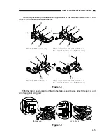
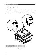
Printer unit receptacle connector mount positioning adjustment
When the printer unit receptacle connector is removed or attached, adjust the mount
position, following the procedure described below.
1) Loosen the 3 receptacle connector screws.
2) Adjust so that the interval between the printer unit frame and the receptacle connec-
tor is 3.5 ± 0.5mm.
Figure 2-10
6.
Check the pressure (nip width) of the fixing pressure roller
This machine has no adjustment mechanism for the fixing assembly nip width.
However, if the nip width is not correct, faulty fixing may occur.
Therefore, check the fixing assembly nip width by following the procedures described
below. If the nip width is outside the standards, replace the fixing assembly.
1) Make one solid black copy on size A3 paper.
2) Place the black side of the paper face down and set the solid black copy in the multi-
feeder.
3) When the leading edge of the paper comes out into the copy tray, quickly switch off
the power source and leave it as is for about 10 seconds.
4) Remove the paper as you would to clear a paper jam from the printer unit.
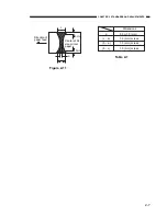
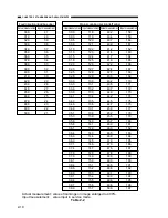
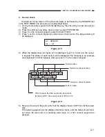
5) Measure the width of the part of the removed paper that is wet and shiny with toner.
Check that the width is within the range displayed in Table 2-1.
3.5
±
0.5mm
Screws
Printer unit
Summary of Contents for GP160DF
Page 6: ...COPYRIGHT 1999 CANON INC CANON GP160 REV 0 FEB 1999 PRINTED IN JAPAN IMPRIME AU JAPON iv...
Page 12: ......
Page 52: ......
Page 64: ......
Page 74: ......
Page 86: ......
Page 88: ......
Page 98: ......
Page 108: ......
Page 110: ......
Page 146: ......
Page 148: ......
Page 158: ......
Page 186: ......
Page 188: ......
Page 204: ......
Page 206: ......
Page 224: ......
Page 232: ......
Page 234: ......
Page 430: ......
Page 432: ......
Page 434: ...A 2 COPYRIGHT 1999 CANON INC CANON GP160 REV 0 FEB 1999 PRINTED IN JAPAN IMPRIME AU JAPON...
Page 436: ......
Page 482: ......
Page 622: ......
Page 623: ......
Page 625: ......
Page 627: ......
Page 635: ......


