CHAPTER 3 ARRANGEMENT AND FUNCTIONS OF THE ELECTRICAL PARTS
3-11
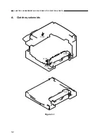
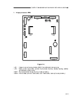
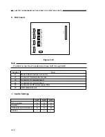
PCBs
* Mounted only in machines with fax function installed.
Table 3-5
Symbol
[1]
[2]
[3]
[4]
[5]
[6]
[7]
[8]
[9]
[10]
[11]
[12]
[13]
[14]
[15]
Name
Image processor PCB
DC controller PCB
Analog processor PCB
Control panel PCB
Control panel sub-PCB
Inverter PCB
Sensor PCB
DC power supply PCB
NCU PCB*
Modem PCB*
Modular PCB*
Laser scanner motor driver
Laser driver PCB
BD PCB
Main motor driver
Function
Image processing
DC load control
CCD drive/analog image processing
Control panel control
Control panel control
Scanning lamp illumination control
Test print switch/leading edge margin adjustment VR
DC power source
Fax transmission control
Fax transmission signal modulation/demodulation
Telephone line connection
Laser scanner motor drive
Laser drive
Laser beam sensor
Main motor drive
Summary of Contents for GP160DF
Page 6: ...COPYRIGHT 1999 CANON INC CANON GP160 REV 0 FEB 1999 PRINTED IN JAPAN IMPRIME AU JAPON iv...
Page 12: ......
Page 52: ......
Page 64: ......
Page 74: ......
Page 86: ......
Page 88: ......
Page 98: ......
Page 108: ......
Page 110: ......
Page 146: ......
Page 148: ......
Page 158: ......
Page 186: ......
Page 188: ......
Page 204: ......
Page 206: ......
Page 224: ......
Page 232: ......
Page 234: ......
Page 430: ......
Page 432: ......
Page 434: ...A 2 COPYRIGHT 1999 CANON INC CANON GP160 REV 0 FEB 1999 PRINTED IN JAPAN IMPRIME AU JAPON...
Page 436: ......
Page 482: ......
Page 622: ......
Page 623: ......
Page 625: ......
Page 627: ......
Page 635: ......


