


CHAPTER 2 STANDARDS AND ADJUSTMENTS
2-4
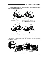
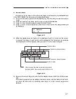
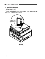
With the mirror positioning tool fitted in the holes shown below, tighten the optical
unit wire pulley’s hexagonal fixing nut.
Figure 2-6
b)
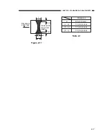
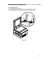
Adjustment of distance between No. 1 and No. 2 mirror mounts
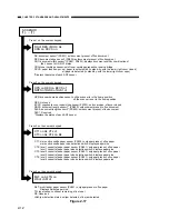
With the optical system wire fixing tool for No. 1 mirror mount loosened, follow the
procedures described below to adjust the distance between No. 1 and No. 2 mirror
mounts, and then tighten the fixing tool.
This adjustment should be performed after the operation to adjust the position of No.
2 mirror mount, as described above.
Figure 2-7
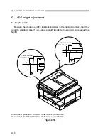
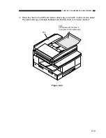
for rear use
for front use
Screw
Screw
Fixing tool
Fixing tool
Summary of Contents for GP160DF
Page 6: ...COPYRIGHT 1999 CANON INC CANON GP160 REV 0 FEB 1999 PRINTED IN JAPAN IMPRIME AU JAPON iv...
Page 12: ......
Page 52: ......
Page 64: ......
Page 74: ......
Page 86: ......
Page 88: ......
Page 98: ......
Page 108: ......
Page 110: ......
Page 146: ......
Page 148: ......
Page 158: ......
Page 186: ......
Page 188: ......
Page 204: ......
Page 206: ......
Page 224: ......
Page 232: ......
Page 234: ......
Page 430: ......
Page 432: ......
Page 434: ...A 2 COPYRIGHT 1999 CANON INC CANON GP160 REV 0 FEB 1999 PRINTED IN JAPAN IMPRIME AU JAPON...
Page 436: ......
Page 482: ......
Page 622: ......
Page 623: ......
Page 625: ......
Page 627: ......
Page 635: ......