Canon DADF-R1 Service Manual Download Page 184

Chapter 5  

5-36

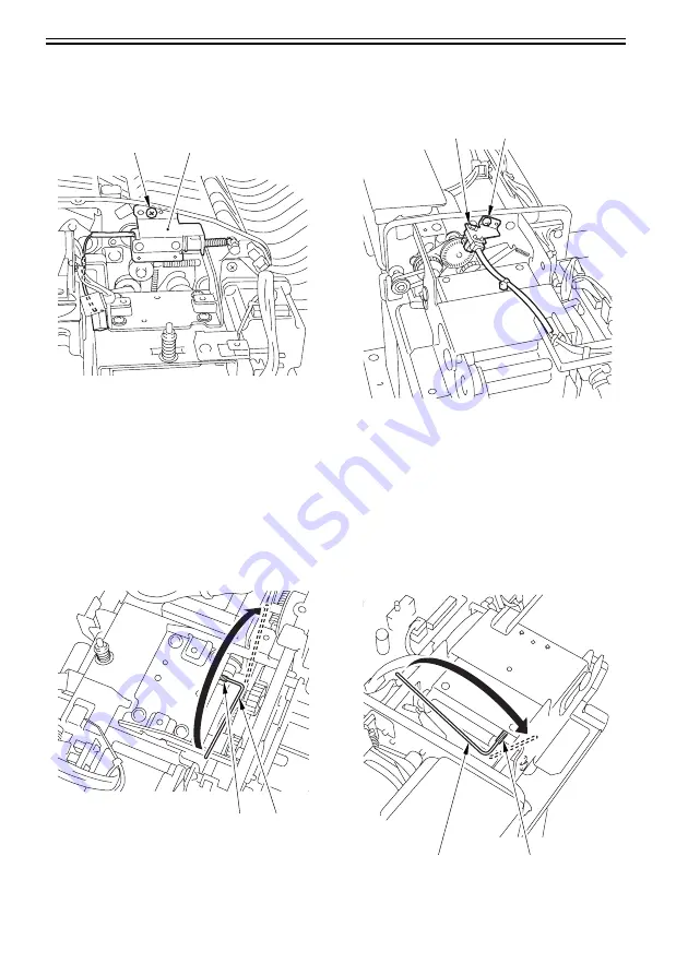
B. How to Adjust the Pressure of Hinge Spring
1. Hinge (left)

1) Unscrew a screw [1] and detach and pre-reversal

solenoid mount [2].

F-5-113

2) Rotate the spring pressure adjusting screw [A] of

the hinge to the direction of the arrow [B] (in a
clockwise direction) using a hex wrench 18 times
by 60 degrees (Max. angle to be rotated per time)
per time (Shorten the spring pressure adjusting
screw [A] by 2 mm).

F-5-114

2. Hinge (right)

1) Unscrew a screw [1] and detach the delivery

motor clock sensor mount [2].

F-5-115

2) Rotate the spring pressure adjusting screw [A] of

the hinge to the direction of the arrow [B] (in a
clockwise direction) using a hex wrench 18 times
by 60 degrees (Max. angle to be rotated per time)
per time (Shorten the spring pressure adjusting
screw [A] by 2 mm).

F-5-116

[1]

[2]

[1]

[2]

[1]

[2]

[1]

[2]

Summary of Contents for DADF-R1

Page 1: ...SERVICE MANUAL DADF R1 COPYRIGHT 2007 CANON INC CANON DADF R1 REV 1 PRINTED IN U S A MAY 2007 DADF_R1 SM cover qxp 5 7 2007 11 07 AM Page 1 Rev 1 ...

Page 2: ......

Page 3: ... need arises In the event of major changes in the contents of this manual over a long or short period Canon will issue a new edition of this manual The following paragraph does not apply to any countries where such provisions are inconsistent with local law Trademarks The product names and company names used in this manual are the registered trademarks of the individual companies Copyright This ma...

Page 4: ......

Page 5: ...quiring care to avoid combustion fire Indicates an item prohibiting disassembly to avoid electric shocks or problems Indicates an item requiring disconnection of the power plug from the electric outlet Indicates an item intended to provide notes assisting the understanding of the topic in question Indicates an item of reference assisting the understanding of the topic in question Provides a descri...

Page 6: ...used to indicate Low The voltage value however differs from circuit to circuit In addition the asterisk as in DRMD indicates that the DRMD signal goes on when 0 In practically all cases the internal mechanisms of a microprocessor cannot be checked in the field Therefore the operations of the microprocessors used in the machines are not discussed they are explained in terms of from sensors to the i...

Page 7: ...R1 imagePRESS C1 Series 2 3 2 2 4 Installing the DADF R1 imagePRESS C7000Series 2 9 2 2 5 Installing the Option Power Supply Unit S1 imagePRESS C1 Series 2 15 2 3 Making Adjustments 2 18 2 3 1 Adjustment imagePRESS C1Series imagePRESS C7000Series 2 18 2 3 2 Adjusting the Right Angle imagePRESS C1Series imagePRESS C7000Series 2 18 2 3 3 Horizontal Registration Adjustment imagePRESS C1Series imagePR...

Page 8: ...ce Absence of an Original in the Manual Feeder 3 18 3 4 Document Pickup Separation 3 19 3 4 1 Outline 3 19 3 4 2 Moving Up Down the Pickup Roller Unit 3 20 3 4 3 Switching the Separation Pressure 3 22 3 4 4 Separation Sensor S4 and Skew Sensor S5 3 23 3 4 5 Controlling the Pickup Motor M3 3 24 3 4 6 Controlling the Separation Motor M4 3 25 3 4 7 Sequence of Operations 3 26 3 5 Document Feeding Del...

Page 9: ...4 3 1 Reversal Motor 4 4 4 3 2 Pickup Motor 4 5 4 3 3 Delivery Motor 4 5 4 3 4 Belt Motor Unit 4 6 4 4 Document Feeding System 4 6 4 4 1 Registration Roller 4 6 4 4 2 Reversing Roller 4 7 4 4 3 Feed Belt 4 9 4 4 4 Separation Belt 4 10 4 4 5 Delivery Roller 4 12 4 4 6 Pickup Rollor 4 14 4 4 7 Separation Rollor 4 15 4 4 8 Feeding pull off Roller 4 17 4 4 9 Document Tray 4 18 4 4 10 Manual Feed Regis...

Page 10: ... 19 Manual Feed Roller Support Member 5 11 5 2 4 20 Delivery Roller Support Member 5 11 5 2 4 21 Manual Feed Registration Roller Support Member 5 11 5 3 Adjustment 5 12 5 3 1 Basic Adjustment 5 12 5 3 1 1 Basic Adjustments 5 12 5 3 1 2 ADF Height Adjustment 5 12 5 3 1 3 ADF Right Angle Adjustment 5 13 5 3 1 4 Horizontal Registration Adjustment 5 14 5 3 1 5 Leading Edge Registration Adjustment 5 17...

Page 11: ...2 1 Alarm 5 42 5 5 Outline of Electrical Components 5 43 5 5 1 Sensors 5 43 5 5 2 Motors Clutches and Solenoids 5 44 5 5 3 PCBs 5 45 5 6 Variable Resistors VR Light Emitting Diodes LED and Check Pins by PCB 5 46 5 6 1 Outline 5 46 5 6 2 ADF Controller PCB 5 46 5 6 3 DIP Switch Functions 5 47 5 6 4 Reversal Motor Driver PCB Belt Motor Driver PCB 5 50 5 6 5 Pickup Tray PCB 5 50 5 6 6 Indication LED ...

Page 12: ...Contents 6 3 Alam Code 6 6 6 3 1 List of Alarm Code 6 6 ...

Page 13: ...Chapter 1 SPECIFICATIONS ...

Page 14: ......

Page 15: ...tents Contents 1 1 Product Specifications 1 1 1 1 1 ADF Specifications 1 1 1 2 Names of Parts 1 3 1 2 1 External View 1 3 1 2 2 Cross Section 1 4 1 3 Using the Machine 1 5 1 3 1 Original Set Indicator 1 5 ...

Page 16: ......

Page 17: ...ght conversion A5 A4 B5 STMT LTR A4R B5R LTRR large size 100 sheets 80 g m2 or less If heavier than 80 g m2 conversion used If longer than 432 mm 1 sheet A3 B4 LGL 279 4X431 8 mm 11 X17 Original reference tray center manual feeder rear Original reading stream single sided fixed Pre cycle end no Control panel no Display no Original AE detection no image processing after reading by host machine 2 on...

Page 18: ...uding delivery tray Dimensions 646 W x 569 5 D x 143 H mm Not including delivery tray Power consumption 100 W or less during operation Operating noise sound pressure host machine 3 dB Host machine ADF finisher alone 72 dB sound quality 10 78 sone 85 ipm DF opening closing noise impact sound pressure 70 dB Operating noise same as host machine Temperature range Humidity range ...

Page 19: ...Chapter 1 1 3 1 2 Names of Parts 1 2 1 External View 0013 3452 F 1 1 1 Upper cover 4 Manual feed tray 2 Side guide 5 Front cover 3 ADF controller cover 1 2 3 4 5 ...

Page 20: ...r 16 Feeding belt 5 Registration roller 17 Stopper plate 6 Pull off roller 18 Separation belt 7 Pull off pressure roller 19 Feed belt driver roller 8 Feeding roller 20 Guide flapper 9 Pickup roller 21 Pre reversal flapper 10 Manual feed registration roller 22 Reversing roller A 11 Manual feed stopper plate 23 Reversing roller A member 12 elivery roller A member 1 2 3 4 5 6 7 8 9 10 11 12 15 14 13 ...

Page 21: ...nd Action to Take If the Original Set indicator starts to flash while an original is inside the DADF suspect a jam go through the following to remove the jam 1 Remove all originals from the original tray 2 Open the upper cover and remove the jam if found 3 Open the DADF and remove the original from the copyboard glass if found 4 Put the originals back into initial sequence and place the stack in t...

Page 22: ......

Page 23: ...Chapter 2 INSTALLATION ...

Page 24: ......

Page 25: ...ments 2 18 2 3 1 Adjustment imagePRESS C1Series imagePRESS C7000Series 2 18 2 3 2 Adjusting the Right Angle imagePRESS C1Series imagePRESS C7000Series 2 18 2 3 3 Horizontal Registration Adjustment imagePRESS C1Series imagePRESS C7000Series 2 19 2 3 4 Leading Edge Registration Adjustment imagePRESS C1Series imagePRESS C7000Series 2 22 2 3 5 Horizontal Registration Adjustment Fine Adjustment imagePR...

Page 26: ......

Page 27: ...ginal delivery tray 1 pc 3 Fan unit 1 pc 4 Fan holder 2 pc 5 Fan duct 2 pc 6 Cover duct 1 pc 7 Electrostatic filter 2 pc 8 Screw Bind M4X30 4 pc 9 Screw P tight M4X10 6 pc 10 Screw RS tight M4X10 2 pc 11 Harness retainer 2 pc 12 Cleaning instruction label only with the products designed for USA EUR 4 pc only with the products designed for AUS ASIA 5 pc 13 Manual Feeder Placement label 1 pc 14 Shee...

Page 28: ...r Supply Unit S1 0013 0957 only for imagePRESS C1 Seires F 2 2 1 Power Supply unit 1 pc 2 Screw Bind M4X6 4 pc 3 Fan relay cable 1 pc 4 DC relay cable 1 pc 5 AC relay cable 1 pc 6 Ferrite core 1 pc The parts is only for the 200V machine 1 2 3 5 4 6 ...

Page 29: ...ct the 2 power plugs of the machine 1 at the for the rear 1 at the left side Power On Order for Turning On the Power When Pickup Delivery Accessories are Connected Be sure to turn on the power in the correct order otherwise it may cause an error because the host machine fails to recognize accessories including this equipment Power On Order 1 Accessories accessories including this equipment 2 Host ...

Page 30: ...ght cover 1 2 screws 2 F 2 4 3 Remove the fan hole covering 1 F 2 5 4 Remove the reader unit fixing plate rear right 1 1 stepped screw 2 2 screws 3 F 2 6 5 Fit the 2 harness retainers 1 F 2 7 Do not use the removed fan hole covering 1 2 1 1 1 2 3 1 ...

Page 31: ...8 7 Likewise perform step 6 for the other fan 8 Lead the cable 1 through the 2 cable guides 2 F 2 9 9 After placing the harness 2 of the fun 1 to face the rear side of the main body fit the fan hole 3 and the emboss 4 F 2 10 Point of caution of fan installation direction A The fan orientation is wrong B The cable guide orientation is wrong 1 4 5 2 3 A B 1 2 1 1 2 3 4 ...

Page 32: ...11 11 Fix the cable 1 in place using 2 harness retainers 2 F 2 12 12 After placing the harness 2 of the fun 1 to face the rear side of the main body fit the fan hole 3 and the emboss 4 F 2 13 13 Fix the fan holder 1 in place Make sure not to get the harness caught by the fan holder 2 screws Bind 4X30 2 F 2 14 1 2 1 2 1 2 3 4 1 1 2 ...

Page 33: ...nect the connector 1 and route the harness 2 through the cable guide 3 16 Fix the harness 4 using the 2 harness retainers 5 F 2 16 17 Fix the harness 1 using the harness retainer 2 as shown F 2 17 18 Mount the 2 fan ducts 1 4 screws P tight M4X10 2 F 2 18 1 2 5 1 2 4 3 2 1 1 2 ...

Page 34: ...Attach the parts which have been detached at the previous steps reader unit fixing plate rear right reader unit upper right cover reader unit right cover 22 Mount the Original delivery tray 1 2 screws RS tight M4X10 2 F 2 21 23 Lift the DADF 1 to fit it into the reader unit F 2 22 1 1 2 Be careful not to pinch your hands between the DADF and the copier 1 2 1 ...

Page 35: ...3 25 Close the DADF 2 2 4 Installing the DADF R1 imagePRESS C7000Series 0016 3327 1 Detach the sub station upper right cover 1 3 screws 3 F 2 24 2 Detach the reader right cover 1 3 screws 2 F 2 25 3 Detach the reader upper right cover 1 2 screws 2 F 2 26 1 1 2 1 2 2 2 1 2 ...

Page 36: ...ht 1 1 stepped screw 2 2 screws 3 F 2 28 6 Fit the 2 harness retainers 1 F 2 29 7 Holding the fan 4 so that the label side 1 faces upward orient it in relation to the cable guides 2 and 3 then fit it in place in the fan holder 5 F 2 30 Do not use the removed fan hole covering 1 1 1 2 3 1 1 4 5 2 3 ...

Page 37: ...of the fun 1 to face the rear side of the main body fit the fan hole 3 and the emboss 4 F 2 32 11 Fix the fan holder 1 Make sure not to get the harness caught by the fan holder 2 screws binding M4X30 2 F 2 33 Point of caution of fan installation direction A The fan orientation is wrong B The cable guide orientation is wrong A B 1 2 1 1 2 3 4 1 2 ...

Page 38: ...rness 2 of the fun 1 to face the rear side of the main body fit the fan hole 3 and the emboss 4 F 2 35 14 Fix the fan holder 1 in place Make sure not to get the harness caught by the fan holder 2 screws binding M4X30 2 F 2 36 15 Lead the cable 1 through the 4 cable guides 2 F 2 37 1 2 1 2 3 4 1 1 2 1 2 ...

Page 39: ... the cable guide 3 17 Fix the harness 4 using the 2 harness retainers 5 F 2 38 18 Fix the harness 1 using the harness retainer 2 as shown F 2 39 19 Mount the 2 fan ducts 1 4 screws P tight M4X10 2 F 2 40 20 Fit the 2 Electrostatic filter 1 in place F 2 41 5 1 2 4 3 2 1 1 2 1 ...

Page 40: ...der upper right cover Reader right cover 23 Mount the document delivery tray 1 2 screws RS tight M4X10 2 F 2 43 24 Attach the sub station upper right cover 1 25 Lift the DADF 1 to fit it into the reader unit F 2 44 26 Close the DADF 27 Fit the cable 1 of the DADF to the host machine F 2 45 1 2 1 2 Be careful not to pinch your hands between the DADF and the copier 1 1 ...

Page 41: ...r 1 F 2 46 2 Open the decurler upper unit 1 F 2 47 3 Move the outer delivery roller cover 1 in the direction of the arrow to detach it 1 screws 2 F 2 48 4 Removing the delivery tray 5 Remove the lower left cover 1 2 face covers 2 3 screws 3 F 2 49 6 Disconnect the connector 1 and the 2 reuse bands 2 F 2 50 1 1 1 2 2 3 1 3 1 2 ...

Page 42: ...51 8 Hold up the handle remove the connector 1 F 2 52 9 Fit the protrusion 1 of the reuse band into the fixing hole 2 Attach the ferrite core 3 Only for the 200V machine F 2 53 10 Connect the connector of the AC relay cable 1 F 2 54 1 1 Take care so that the harness is not trapped by the ferrite core 1 2 3 1 ...

Page 43: ... F 2 58 15 Lift the grip to connect the 2 connectors 2 of the DC relay cable 1 16 Fix the 4 cables in place using 3 wire saddles 3 F 2 59 17 Attach the parts which have been detached at the previous steps lower left cover face cover delivery tray outer delivery roller cover decurler upper unit decurler front cover 18 Connect the host machine s 2 power plugs back left to 2 separate power supply sys...

Page 44: ...the Right Angle imagePRESS C1Series imagePRESS C7000Series 0013 0259 Here the original feed direction of the machine is adjusted in relation to the optical system of the host machine 1 Prepare a test chart as shown using A4 or LTR copy paper F 2 60 2 Place the test chart 1 prepared above in the original tray and make a copy in stream reading mode at 100 magnification F 2 61 3 Place other copy pape...

Page 45: ...ment for the following 2 pickup from the original tray See A for details pickup from the manual feeder tray See B for details A Pickup from the Original Tray 1 Remove the DADF controller cover 1 1 screw 2 F 2 64 2 Set the DIP switch SW1 on the DADF controller PCB as follows F 2 65 3 Turn OFF the power 4 Place a single sheet of A4 or LTR copy paper 1 in the original tray F 2 66 5 Press the push swi...

Page 46: ...ition of the original tray 1 Loosen the tray fixing screw 1 and adjust the position of the original tray 2 If C 3 1 mm for A4 11 9 for LTR move the original tray toward the rear If C 3 1 mm for A4 11 9 for LTR move the original tray toward the front F 2 69 2 When done tighten the original tray fixing screw 3 Put the DIP switch SW1 of the ADF controller PCB back to its initial configuration and mou...

Page 47: ...e In response the original will be discharged to the delivery tray 8 When done tighten the manual feeder tray fixing screw 9 Put the DIP switch SW1 on the DADF controller PCB back to its initial configuration and attach the DADF controller cover If Not as Indicated If the dimension is not as indicated adjust the position of the manual feeder tray 1 Loosen the manual feeder tray fixing screw 1 and ...

Page 48: ...up from the manual feeder tray See B for details pickup from the original tray small size stream reading See C for details A Pickup from the Original Tray 1 Remove the DADF control cover 1 1 screw 2 F 2 77 2 Set the DIP switch SW1 on the DADF controller PCB as follows F 2 78 3 Turn ON the power 4 Place a single sheet of A4 or LTR copy paper 1 in the original tray F 2 79 5 Press the push switch SW2...

Page 49: ...copyboard glass by 12 mm Keeping the copy paper on the copyboard glass close the DADF To change the stop position to the left by 1 mm press the push switch SW4 twice 1 0 5 2 then press the push switch SW2 The copy paper will be discharged and the change will be saved 9 Put the DIP switch SW1 of the ADF controller PCB back to its initial configuration and mount the ADF controller cover Switch Direc...

Page 50: ...nd set A4 or LTR paper 2 in it But the paper 1 against the rear side 3 of the manual feed tray F 2 86 F 2 87 5 Press the push switch SW2 on the DADF controller PCB once In response the original will be picked up and stopped on the copyboard cover F 2 88 6 Lift the DADF and see that D in the figure is 11 1 mm F 2 89 2 1 1 2 3 J1 J2 J5 J3 J6 J7 J8 J9 J10 J16 J15 J11 J14 IC8 J13 J12 J4 CB1 SW1 DSP1 S...

Page 51: ...h SW2 The copy paper will be discharged and the change will be saved 9 Put the DIP switch SW1 of the ADF controller PCB back to its initial configuration and mount the ADF controller cover C Document Tray Pickup small size stream reading 1 Turn ON the power 2 Set either one A4 document or LTR document 1 on the document tray and execute copy F 2 92 3 Compare the document and the print image to chec...

Page 52: ...nual feed tray pickup See B for details When executing this adjustment use the service mode The adjustment value is stored in the DADF controller PCB A Document Tray Pickup 1 Turn ON the power 2 Set either one A4 document or LTR document 1 on the document tray and execute copy F 2 95 3 Compare the document and the print image to check that displacement of the horizontal registration is 1 mm or les...

Page 53: ...ray pickup the 1st side See A for details Document tray pickup the 2nd side See B for details When executing this adjustment use the service mode The adjustment value is stored in the DADF controller PCB A Document Tray Pickup the 1st side 1 Set either one A4 document or LTR document 1 on the document tray and execute double sided copy F 2 100 2 For the subsequent procedure follow A Document Tray ...

Page 54: ...on the cleaning instructions label 1 on the upper rear cover as shown and attach it F 2 101 2 4 2 Attaching the Manual Feeder Placement Label imagePRESS C1Series imagePRESS C7000Series 0013 1545 1 Open the manual feeder 1 of the DADF and position and attach the manual feeder placement label 2 Be sure to select the correct language F 2 102 1mm 1mm 1 2 1 ...

Page 55: ...FUNCTIONS Chapter 3 ...

Page 56: ......

Page 57: ...t Pickup Separation 3 19 3 4 1 Outline 3 19 3 4 2 Moving Up Down the Pickup Roller Unit 3 20 3 4 3 Switching the Separation Pressure 3 22 3 4 4 Separation Sensor S4 and Skew Sensor S5 3 23 3 4 5 Controlling the Pickup Motor M3 3 24 3 4 6 Controlling the Separation Motor M4 3 25 3 4 7 Sequence of Operations 3 26 3 5 Document Feeding Delivery 3 26 3 5 1 Outline 3 26 3 5 2 Controlling the Belt Motor ...

Page 58: ...Contents 3 7 Detecting Jams 3 57 3 7 1 Overview 3 57 3 7 2 List of Jam Code 3 58 3 7 3 Alarm Code 3 61 3 8 Power Supply 3 62 3 8 1 Overview 3 62 ...

Page 59: ...nals from sensors and the host machine and generates appropriate signals to drive such loads as motors and solenoids at such times as programmed in advance F 3 1 CPU Q1 ROM IC1 EEPROM IC2 RAM Q4 D A Q9 IPC Q2 5V 24V 5R 24R Power supply PCB Copier Solenoid Clutch Original indicator LED PCB Sub tray PCB Reversal motor driver PCB Belt motor driver PCB Motor Sensor Motor Motor ADF controller PCB DC5V ...

Page 60: ...of the separation motor When the paper cover is closed 1 When paper is present 1 Pulses according to the rotation speed of the registration roller When the upper cover is closed 1 When the pickup roller is in home position 1 When the pickup roller is on paper 1 When the pickup roller is on paper 1 When the DADF is closed 1 Pulses according to the rotation speed of the delivery motor When paper is ...

Page 61: ... registration roller paper sensor Post registration roller paper sensor Separation sensor Skew sensor Original sensor light receiving Original sensor light emitting Original trailing edge sensor Manual feed registration roller paper sensor ADF controller PCB Reference signal for paper detection When paper is present 0 Reference signal for paper detection When paper is present 0 Reference signal fo...

Page 62: ... 5V M2OB M2OA M2OB M2OA B Vref J7 8 10 1 2 3 4 5 6 M2 J71 J72 Separation clutch Reversal solenoid Stopper plate solenoid 2 position Pre reversal solenoid Delivery solenoid 2 position Reversal motor Belt motor Pickup motor Separation motor Delivery motor ADF controller PCB When 0 the separation clutch goes on When 0 the solenoid goes on When 0 the solenoid goes on position 1 When 0 the solenoid goe...

Page 63: ...the pull off roller and the separation feed drive system PI 2 PI 1 PI 5 PI 11 SL3 SL1 SL2 SL4 M5 Pre reversal solenoid drive signal SL1D Separation motor clock signal SPCLK Separation motor drive signal Separation clutch drive signal CLD Stopper solenoid drive signal 2 SL2D2 Stopper plate solenoid signal 1 SL2D1 Pickup motor drive signal Belt motor drive signal Belt motor clock signal BTCLK Revers...

Page 64: ...ignal Separation paper detection signal SPS Skew paper detection signal SKS Pickup roller home position signal Pickup roller height 1 signal 2 signal Left cover rear signal Left cover front signal Original sensor light emission signal Original detection signal Original placement indication light emission signal Original width detection signal Original trail edge detection signal RF open closed det...

Page 65: ...No Mode Operation Copying mode Copying operation 1 CW pickup delivery Picks up an original and delivers it as it is after copying Single sided original to single sided copy Signal sided original to double sided copy Stream reading fixed if the reproduction ratio is not between 50 and 200 2 Pre reversal pickup reversal delivery Reverses an original picks it up reverses it once again after copying a...

Page 66: ...Chapter 3 3 8 3 2 4 Pre Reversal Reversal Delivery 0013 3465 The following is an outline of the flow of originals F 3 10 Picking up Pre reversing Feeding Copying the 1st side Moving To next page ...

Page 67: ...Chapter 3 3 9 F 3 11 Reversing Copying the 2nd side Delivering From previous page ...

Page 68: ...Chapter 3 3 10 3 2 5 Manual Feeder Pickup Delivery 0013 3466 The following is an outline of the flow of originals F 3 12 Picking up Stopping Switching back Copying Delivering ...

Page 69: ...riginal tray Original sensor S6 Original size 1 Identifies the size of the original placed in the original tray as to being large size or small size Original trailing edge sensor S7 Original size 2 Identifies the size of an original on the move default size Registration roller clock sensor PI5 Original in manual feeder Detects the presence absence of an original in the manual feeder Manual feeder ...

Page 70: ...ed causing the light receiving side of the original sensor to send the original detection signal DTS to the ADF controller PCB which in response turns on the Original Set indicator F 3 14 ADF controller PCB S6 light receiving side S6 light emitting side S6 light receiving side ADF controller PCB When an original is detected When no original is detected S6 light emitting side S6 light receiving sid...

Page 71: ...t the phototransistor at which time the DADF identifies the original as being large size The DADF sends original size data small size or large size to the copier which uses the data to determine the point at which the scanner is stopped for stream reading F 3 15 Small size A5 A4 B5 STMT LTR Large size A4R B5R A3 B4 LTRR LGL 279 4X431 8mm 11 X17 ADF controller PCB ADF controller PCB If the original...

Page 72: ... communicated to the ADF controller PCB which uses the input to determine the width of the original The following table shows the states of the contact plates in relation to default sizes the states other than those indicated are assumed to indicate the presence of an original which is not of a default size F 3 16 T 3 3 Default size SSW0 SSW1 SSW2 SSW3 SSW4 A5 A4R ON ON OFF ON ON ON OFF OFF ON ON ...

Page 73: ...ult size and sends the result to the copier In response the copier selects the appropriate copy paper size to suit the identified size of the original The following tables show the default sizes in relation to the sizes detected by the DADF T 3 4 A and A B Configuration T 3 5 unit mm Default size Original length Original width B5R 237 to 297 180 to 184 A5 128 to 188 208 to 212 A4R 277 to 317 FOOLS...

Page 74: ...ide of the above ranges will be identified as a non default size unit mm Default size Original length Original width B5R 237 to 297 180 to 184 A5 128 to 188 208 to 212 A4R 277 to 337 STMT 120 to 180 213 9 to 217 9 LTRR 259 to 309 FOOLSCAP 310 to 343 LGL 343 to 396 B5 162 to 222 255 to 259 B4 344 to 404 LTR 196 to 256 277 4 to 281 4 279 4X431 8 11 X17 412 to 472 A4 190 to 250 295 to 299 A3 400 to 4...

Page 75: ...s provided with notches to make sure that the slide guide stops to suit a specific default original size Some of these points representing differing paper sizes however are close enough to allow the slide guide to be set at the wrong point To prevent wrong positioning of the slide guide the DADF comes with two types of slide guide positioning members when fitted correctly the positioning members w...

Page 76: ...al pushes the sensor flag causing the sensor flag to reach the sensor enabling the DADF to assume the presence of an original in the manual feeder When the Start key is pressed the DADF picks up the original from the manual feeder for copying F 3 20 Slide guide positioning member gray Slide guide positioning members black Relocate Relocate For Inch configuration For A B configuration Slide guide p...

Page 77: ...M4 and the separation clutch CL Originals are separated by the separation roller and the separation belt with the help of the feeding roller The rollers and the belt are driven by the separation motor M4 and the separation clutch CL The separation assembly is equipped with a separation sensor S4 and a skew sensor S5 to monitor the movement of originals F 3 21 Feeding roller Feeding belt CL Feeding...

Page 78: ...sitioning is controlled by means of pulses from sensors and the pickup motor T 3 8 F 3 22 Stop position Operation Related sensor notation Home position Waits until the next copying operation Pickup roller home position sensor PI7 Wait position Waits until the next pickup position Pickup height sensor 1 2 PI8 9 Pulse control of pickup motor M3 Pickup position Picks up originals Pickup height sensor...

Page 79: ... down about 1 mm F 3 23 When the pickup roller unit stops to move down the separation clutch CL and the separation motor M3 start to move the 1st original to the separation assembly F 3 24 When the leading edge of the 1st original reaches the separation sensor S4 the pickup motor M3 starts to rotate to move the pickup roller unit from the surface of the stack of originals The pickup roller unit st...

Page 80: ...ed with a separation pressure switching mechanism which enables switching between two settings low or high The separation pressure may be switched by operating the separation pressure lever located in front of the separation assembly When the lever is operated the position of the separation belt moves up or down to change the amount of overlap in relation to the feeding roller thereby varying the ...

Page 81: ...ection An original is identified as moving askew if a discrepancy in timing is detected when it moves past these sensors If the discrepancy is an equivalent of 10 mm the DADF will assume that the original is moving askew at which point it stops its operation to protect the original and causes the copier to indicate a jam message Item Sensor used notation Alarm Separation fault delay Separation sen...

Page 82: ...ntrols the output timing of the pulse signals accordingly switching over the direction of motor rotation PICKI0 PICKI1 is a current setup signal and its variation combination enables a switch over among 4 steps from 0 to 100 PICKSTBY is a motor standby signal and is used to turn off the motor drive circuit during which time no phase signal is sent to the motor Error code E410 fault in the pickup m...

Page 83: ...rriving rotation speed signal against the speed reference signal SEPCLKREF from the CPU and sends the result as the speed control signal SPMFV to the CPU Using the arriving speed control signal the CPU varies the rotation speed signal LED3 goes on when the motor rotation speed is within a specific range while going off if out of the range The current detection circuit monitors the current flowing ...

Page 84: ... delivery motor M5 Originals are always delivered to the original delivery tray F 3 32 Start key ON Original sensor S6 Pickup roller home position sensor PI 7 Pickup roller height sensor 1 2 PI 8 9 Pickup motor M3 Separation motor M4 Separation clutch CL Separation sensor S4 Skew sensor S5 UP DOWN UP UP DOWN Picking up separating 1st original Picking up separating 2nd original End Pickup roller sh...

Page 85: ...tor control signals to the belt motor driver PCB which in turn controls the motor as instructed by these signals T 3 9 Error code E402 fault in the belt motor M2 fault in the belt motor clock sensor PI1 fault in the ADF controller PCB Signals Description INA phase control direction and speed of rotation INB phase control direction and speed of rotation IN_A phase control direction and speed of rot...

Page 86: ...e control block which in turn generates the motor drive signal EJMD in keeping with the arriving signal The rotation of the motor generates the motor rotation signal EJCLK used by the CPU to monitor the operation of the motor T 3 10 Error code E404 fault in the delivery motor M5 fault in the delivery motor clock sensor PI11 fault in the ADF controller PCB Related adjustment sensor delivery motor a...

Page 87: ...inal is held in place on the copyboard glass and is read by the scanner being moved by the host machine Specifically A Single Sided Original 1 The machine picks up the 1st original and butts its lead edge against the registration roller to remove the skew For details of pickup operation see Original Pickup Separation F 3 35 Operation Mode of operation Printing mode Printing mode fixed reading sing...

Page 88: ...t over a specific distance after its trail edge has moved past the pre registration roller sensor S2 determining the original stop position F 3 37 4 The host machine starts printing operation using its scanner F 3 38 5 When the host machine s scanner starts to move in reverse the machine rotates the transport belt in reverse to move the 1st original in the direction of delivery At the same time th...

Page 89: ...Operation single sided original F 3 41 Pre registration roller paper sensor S2 2nd original 1st original COPY Start key ON Original sensor S6 Pickup roller home position sensor PI 7 Pickup roller height sensor 1 2 PI 8 9 Stopper plate solenoid SL2 Pickup motor M3 Separation motor M4 Separation clutch CL Reversal motor M1 Belt motor M2 Delivery motor M5 UP DOWN UP DOWN UP UP DOWN separates 1st orig...

Page 90: ...hine rotates the registration roller and the transport belt to move the 1st original F 3 43 3 The machine places the 1st original on the copyboard The host machine starts to scan the original F 3 44 4 The machine uses the transport belt and the delivery roller to discharge the 1st original The host machine moves the scanner in reverse F 3 45 Registration roller 1st original Registration roller Tra...

Page 91: ... 1 The machine picks up the 1st original and butts its lead edge against the registration roller to remove the skew For details of pickup operation see Original Pickup Separation F 3 48 2nd original Start key ON Original sensor S6 Pickup roller home position sensor PI 7 Pickup roller height sensor 1 2 PI 8 9 Stopper plate solenoid SL2 Pickup motor M3 Separation motor M4 Separation clutch CL Revers...

Page 92: ...it has moved past the pre registration roller sensor S2 F 3 50 4 The machine rotates the transport belt to move the original over a specific distance The host machine reads the original When the machine has moved the 1st original based on the count reading started after the trail edge of the original has moved past the pre registration roller paper sensor S2 the machine sends the image lead edge s...

Page 93: ...s B Sequence of Operation small size original F 3 53 2nd original UP DOWN UP DOWN UP UP DOWN separates 1st original holds 1st original in standby separates 2nd original reads 1st original holds 2nd original in standby separates 3rd original discharges 1st original reads 2nd original holds 3rd original in standby discharges 2nd original reads 3rd original discharges 3rd original A4 Single Sided Ori...

Page 94: ... original if the original is 279 4 x 431 8 mm 11x17 after the original starts to move in 4 F 3 55 3 When the lead edge of the original has moved past the post registration roller paper sensor S3 the machine rotates the transport belt over a specific distance and stops the original standby position At this time the machine starts to keep track of the distance over which the 1st original moves after...

Page 95: ...2nd original F 3 57 5 The machine rotates the transport belt motor to move the 2nd original If the read signal arrives from the host machine before the 2nd original arrives in front of read position 25 mm stop distance the machine does not stop the 2nd original for reading If the signal does not arrives in front of read position 25 mm stop distance on the other hand the machine stops the original ...

Page 96: ...height sensor 1 2 PI 8 9 Stopper plate solenoid SL2 Pickup motor M3 Separation motor M4 Separation clutch CL Reversal motor M1 Belt motor M2 Delivery motor M5 UP DOWN UP UP DOWN separates 1st original reads and discharges 1st original moves 2nd original to standby position reads 2nd original discharges 2nd original moves 1st original to standby position separates 2nd original A3 2 Single Sided Ori...

Page 97: ... over which the 1st original moves after it has moved past the pre registration roller paper sensor S2 F 3 62 4 The machine rotates the transport belt to move the original over a specific distance and discharges it reading takes place here F 3 63 5 When the 1st original has fully been discharged the machine starts pickup of the 2nd original F 3 64 6 The machine goes back to step 2 and repeats the ...

Page 98: ...al Pickup Separation F 3 66 Start key ON Original sensor S6 Pickup roller home position sensor PI 7 Pickup roller height sensor 1 2 PI 8 9 Stopper plate solenoid SL2 Pickup motor M3 Separation motor M4 Separation clutch CL Reversal motor M1 Belt motor M2 Delivery motor M5 UP DOWN UP UP DOWN picks up 1st original reads and discharges 1st original picks up 2nd original reads and discharges 2nd origi...

Page 99: ...ces the original on the copyboard glass F 3 67 3 As the host machine moves its scanner in reverse the machine moves the original to the reversing path F 3 68 4 The machine turns over the 1st original and places it on the copyboard glass F 3 69 F 3 70 1st original 1st original 1st original 1st original ...

Page 100: ...l F 3 71 6 The 1st original turns over the 1st original once again F 3 72 7 The machine discharges the 1st original F 3 73 8 The machine places the 2nd original on the copyboard glass F 3 74 1st original 1st original 1st original 2nd original 1st original 2nd original ...

Page 101: ...N UP A4 2 Double Sided Originals Scan picks up 1st original turns over 1st original turns over 2nd original reads face of 1st original turns over 1st original discharges 1st original picks up 2nd original reads back of 1st original reads face of 2nd original reads back of 2nd original turns over 2nd original discharges 2nd original Start key ON Original sensor S6 Pickup roller home position sensor...

Page 102: ...it F 3 78 3 The machine uses the reversing roller and the transport belt to move the original The machine rotates the transport belt over a specific distance after the trail edge of the 1st original has moved past the reversal sensor S1 thus determining the original stop position F 3 79 4 The host machine s scanner starts to read the original as part of printing operation F 3 80 Pre registration r...

Page 103: ...e 1st original has moved past the pre registration roller paper sensor S2 the machine moves the original over a specific distance using the transport belt F 3 82 7 The host machine s scanner starts to scan the original as part of printing operation At this time the machine picks up the 2nd original and executes pre reversal See steps 1 and 2 F 3 83 8 When the host machine s scanner starts to move ...

Page 104: ...to copyboard glass reads back of 1st original reads back of 2nd original turns over 1st original separates 2nd original turns over 2nd original separates 3rd original reads face of 1st original pre reversal for 2nd original reads face of 2nd original pre reversal for 3rd original reads back of 3rd original turns over 3rd original reads face of 3rd original moves 3rd original to copyboard glass dis...

Page 105: ... of pickup operation see Original Pickup Separation F 3 88 2 As soon as the original is placed on the copyboard glass the host machine starts to read it using its scanner F 3 89 3 The machine sends the original to the reversing path as the host machine moves its scanner in reverse F 3 90 4 The machine turns over the 1st original and places it on the copyboard glass F 3 91 Registration roller 1st o...

Page 106: ...riginal F 3 93 6 The machine turns over the 1st original once again F 3 94 7 The machine starts to pick up the 2nd original when the trail edge of the 1st original moves past the registration roller F 3 95 1st original 1st original 1st original 1st original 2nd original ...

Page 107: ...nals Scan picks up 1st original turns over 1st original turns over 2nd original reads face of 1st original turns over 1st original again discharges 1st original picks up 2nd original reads back of 1st original reads face of 2nd original reads back of 2nd original reads back of 2nd original turns over 2nd original again Start key ON Original sensor S6 Pickup roller home position sensor PI 7 Pickup ...

Page 108: ...kew For details of pickup operation see Original Pickup Separation F 3 99 2 The machine places the original on the copyboard glass F 3 100 3 The machine sends the original to the reversing path F 3 101 4 The machine turns over the 1st original and places it on the copyboard glass F 3 102 Registration roller 1st original 1st original 1st original 1st original ...

Page 109: ... original F 3 104 6 The machine sends the original to the reversing path as the host machine moves its scanner in reverse F 3 105 7 The machine turns over the 1st original and places it on the copyboard glass F 3 106 1st original 1st original 1st original 1st original ...

Page 110: ...nd read its face F 3 108 9 The machine sends the original in the direction of the delivery roller while the host machine moves its scanner in reverse F 3 109 10 The machine discharges the 1st original while placing the 2nd original on the copyboard glass F 3 110 1st original 1st original 1st original 1st original 2nd original ...

Page 111: ...riginal moves 2nd original to copyboard glass turns over 2nd original turns over 2nd original UP A3 2 Double Sided Originals Printing Reversing solenoid SL1 Original sensor S6 Pickup roller home position sensor PI 7 Pickup roller height sensor 1 2 PI 8 9 Stopper plate solenoid SL2 Pickup motor M3 Separation motor M4 Separation clutch CL Reversal motor M1 Belt motor M2 Delivery motor M5 motor rever...

Page 112: ...r clock sensor The CPU Q18 on the ADF controller PCB sends various motor control signals to the reversal motor driver PCB which in turn controls the motor as dictated by these signals T 3 12 Signal name Description INA phase control direction and speed of rotation INB phase control direction and speed of rotation IN_A phase control direction and speed of rotation IN_B phase control direction and s...

Page 113: ... lead edge of the original butts against the manual feeder registration roller thus removing the skew F 3 115 3 The machine moves the original to move the delivery roller and the transport belt The original stops when its lead edge reaches the reversal sensor S1 F 3 116 4 The machine rotates the transport belt The original is moved over a specific distance after its trail edge has moved past the r...

Page 114: ...ery roller thus moving the original to the delivery assembly F 3 119 Sequence of Operation F 3 120 Copy Start key ON Original placed in manual feeder Belt motor M2 Delivery solenoid M5 Reversal solenoid SL4 Manual feeder placement sensor PI 12 Reversal sensor SL1 Original delivery sensor PI 1 Original placed in manual feeder PI 13 pickup print discharge move original placed 0 4 sec approx ...

Page 115: ...ommunicates the fact to the host machine which in turn indicates the fact in service mode in the form of a code A check may also be made with reference to the indicator DSP1 of the machine s ADF control PCB Service Mode Screen of the Host Machine F 3 121 The indicator DSP1 of the machine s controller PCB flashes 4 times to indicate a specific jam type EX if code is 0013 F 3 122 F 3 123 Jam code 1 ...

Page 116: ...f delivery the manual feeder registration roller sensor detects the original when it has been moved over a specific distance original length 100 mm after the delivery sensor has gone on 0009 delivery stationary 2 PI13 S9 At time of delivery the delivery sensor detects the original when it has been moved over a specific distance 100 mm after the manual feeder registration roller sensor has gone off...

Page 117: ...nal before the reversal motor has started At time of reversal the pre registration roller sensor does not detect the original when its trail edge moves past the reversal sensor 0026 reversal pickup edge skew S4 S5 At time of pre reversal there is a discrepancy of 10 mm in timing of trail edge detection between separation sensor and skew sensor 0027 reversal pickup NG1 PI4 At time of reversal the p...

Page 118: ...1st sheet 0062 1st sheet pickup lead edge skew S4 S5 A pickup lead edge skew condition 0022 has occurred on the 1st sheet 0063 1st sheet pickup trail edge skew S4 S5 A pickup trail edge skew condition 0023 has occurred on the 1st sheet 0064 1st sheet pickup NG1 S1 A pickup NG1 condition 0024 has occurred on the 1st sheet 0065 1st sheet pickup NG2 S2 S3 A pickup NG2 condition 0025 has occurred on t...

Page 119: ...ine is in operation 0092 cover open PI3 PI6 A cover open condition front or rear has been detected 0093 user cover open PI3 PI6 While the machine is operating a sensor in the paper path has detected an original 0094 initial stationary PI4 PI12 PI13 S1 S2 S3 S4 S5 S9 At the start of operation the presence of an original has been detected by a senser in the paper path 0095 cycle NG S6 While no senso...

Page 120: ...of a circuit breaker CB1 Of the 24V power supplied to the loads 24U is sent by way of a fuse while 24R is sent directly The 13 V power is converted into 5 V for sensors by a regulator IC IC15 Another regulator IC IC26 is used to convert 5 V into 3 3 V which is used to drive the ADF controller PCB F 3 124 1 Host machine 2 ADF controller PCB 3 Motors clutches solenoids 4 Sensors CB1 IC15 3 3V FU6 IC...

Page 121: ...PARTS REPLACEMENT PROCEDURE Chapter 4 ...

Page 122: ......

Page 123: ...ve System 4 3 4 3 1 Reversal Motor 4 4 4 3 2 Pickup Motor 4 5 4 3 3 Delivery Motor 4 5 4 3 4 Belt Motor Unit 4 6 4 4 Document Feeding System 4 6 4 4 1 Registration Roller 4 6 4 4 2 Reversing Roller 4 7 4 4 3 Feed Belt 4 9 4 4 4 Separation Belt 4 10 4 4 5 Delivery Roller 4 12 4 4 6 Pickup Rollor 4 14 4 4 7 Separation Rollor 4 15 4 4 8 Feeding pull off Roller 4 17 4 4 9 Document Tray 4 18 4 4 10 Man...

Page 124: ......

Page 125: ...pen the DADF fully 4 Standing at the rear of the copier lift the DADF to detach F 4 2 4 2 External Covers 4 2 1 External Covers 4 2 1 1 External Covers 0013 3526 1 Body front cover 2 Main cover 3 Original tray 4 Upper cover 5 ADF controller cover F 4 3 4 2 2 Front Cover 4 2 2 1 Removing the Front Cover 0013 3527 1 Remove the front cover 1 3 screws 2 remove 1 screw 3 loosen F 4 4 1 Lift 5 1 4 3 2 ...

Page 126: ... the pickup assembly cover 2 from the right stay then detach it while paying attention to the hooks on the front and rear side plates F 4 8 3 When you have removed the ADF controller cover disconnect the connector 3 of the ADF controller PCB then remove the screw 4 and remove the grounding wire 5 Free the harness from the wire saddle 6 and detach the other saddle 7 F 4 9 1 1 2 Hooks Push Freed 3 5...

Page 127: ...ginal tray is equipped with a side guide lock 1 which is fitted into the groove of the tray When the lock is in the groove the tray is set to A3 A4 otherwise the tray may accommodate originals as wide as 305 mm F 4 12 4 3 Drive System 4 3 1 Reversal Motor 4 3 1 1 Preparation for Removing the Reversal Motor Unit 0013 3530 1 Remove the front cover 2 Remove the main cover 4 3 1 2 Removing the Reversa...

Page 128: ...r unit 4 3 2 2 Removing the Pickup Motor Unit 0013 3539 1 Disconnect J601 1 and J602 2 and free the cable from the edge saddle 3 2 Locate the harness connected to the belt motor and free it from the wire saddle 3 F 4 15 3 Remove the 2 screws 1 and detach the belt motor driver PCB unit 2 F 4 16 4 Detach the fan mtor unit 1 by removing the 2 screws 2 F 4 17 5 Disconnect the pick up motor unit 1 conn...

Page 129: ... 2 Removing the Delivery Motor 0013 3542 1 Remove the screw 1 from the bottom of the DADF and remove the bearing 2 and the rod 3 F 4 20 2 Remove the 5 screws 1 and detach the hinge right 2 F 4 21 3 Remove the screw 1 and detach the delivery motor sensor 2 F 4 22 4 Remove the delivery motor 4 1 Remove the grip ring 1 and detach the lock plate 2 4 2 Remove the E ring 3 and remove the belt retaining ...

Page 130: ...3 4 2 Removing the Belt Motor Unit 0013 3547 1 Remove the 3 screws 1 and detach the belt motor unit 2 F 4 24 4 4 Document Feeding System 4 4 1 Registration Roller 4 4 1 1 Preparation for Removing the Registration Roller 0013 3555 1 Remove the front cover 2 Remove the main cover 4 4 1 2 Removing the Registration Roller 0013 3557 1 Remove the 2 screws 1 and detach the reversing guide 2 When mounting...

Page 131: ...the registration roller 1 front side plate F 4 28 4 Remove the E ring 2 gear 3 E ring 4 and bearing 5 of the registration roller 1 rear side plate The gear holds a pin Take care not to lose it when removing the gear F 4 29 4 4 2 Reversing Roller 4 4 2 1 Preparation for Removing the Reversing Roller 0013 3559 1 Remove the front cover 2 Remove the main cover 3 Remove the reversal motor unit 1 1 2 Re...

Page 132: ...g guide do so while forcing it in the direction of the arrow If not properly mounted it can trigger jams F 4 31 3 Remove the reversing roller 3 1 Remove the E ring 2 gear 3 and parallel pin 4 on the rear side plate side of the reversing roller 1 2 pc F 4 32 The gear holds a pin Take care not to lose it when removing the gear 3 2 Remove the grip ring 2 and the bearing 3 on the front side plate side...

Page 133: ... 4 4 3 1 Preparation for Removing the Feeding Belt 0013 3563 1 Remove the front cover 4 4 3 2 Removing the Feeding Belt 0013 3565 1 Turn the releasing lever 1 clockwise to decrease the tension of the belt F 4 35 2 Turn the releasing levers left right 1 outward after removing the 2 fixing screws 2 each F 4 36 F 4 37 3 Detach the feeding belt 1 F 4 38 5 4 1 1 4 5 1 2 1 2 1 1 ...

Page 134: ...n the belt F 4 39 4 4 4 Separation Belt 4 4 4 1 Preparation for Removing the Separation Belt 0013 3566 1 Remove the front cover 2 Remove the main cover 4 4 4 2 Removing the Separation Belt 0013 3567 1 Remove the 2 screws and loosen the separation unit 2 Remove the grip ring 1 at the front then remove the clutch ring 2 and the clutch 3 F 4 40 3 Disconnect the 2 connectors 1 and remove the 2 screws ...

Page 135: ... Loosen the screw 3 on the separation pressure adjusting lever 2 of the separation roller 3 F 4 44 When mounting the separation pressure adjusting lever be sure that the lever is set to low F 4 45 6 Loosen the screw 3 on the thrust stopper 2 of the separation roller 1 F 4 46 1 1 2 3 1 2 High Low 2 1 3 ...

Page 136: ...1 to detach the separation belt 3 F 4 48 4 4 5 Delivery Roller 4 4 5 1 Preparation for Removing the Delivery Roller 0013 3568 1 Disconnect the DADF 2 Remove the front cover 3 Remove the main cover 4 4 5 2 Removing the Delivery Roller 0013 3569 1 Remove the screw 1 from the bottom of the DADF and remove the bearing 2 and the rod 3 F 4 49 2 Remove the 5 screws 1 and detach the hinge right 2 F 4 50 1...

Page 137: ...nect the connector 2 then detach the solenoid unit 3 from the delivery assembly front side plate F 4 53 7 Remove the screw 1 and detach the delivery sensor support plate 2 on the delivery assembly rear side plate side F 4 54 8 Remove the screw 1 and detach the delivery guide support plate 2 on the delivery assembly rear side plate side F 4 55 9 Remove the screw 1 and detach the delivery lower guid...

Page 138: ...ove the E ring 4 then remove the screw 5 and the bushing 6 F 4 57 13 Shift down the delivery lower guide 1 and slide out the delivery roller 2 together with the manual feed tray 3 F 4 58 4 4 6 Pickup Rollor 4 4 6 1 Removing the Pickup Roller 0013 3571 1 Open the upper cover and insert a screwdriver from above the hook then remove the 2 hooks 1 F 4 59 2 Remove pickup assembly cover 1 F 4 60 1 2 3 5...

Page 139: ...nt cover 2 Remove the main cover 4 4 7 2 Removing the Separation Roller 0013 3573 1 Remove the 2 screws 1 and detach the sensor stay 2 2 Remove the 3 screws 3 and detach the 3 guide plates 5 from the right stay 4 F 4 62 3 Remove the 2 screws 1 and detach the lower guide 2 F 4 63 F 4 64 4 Remove the grip ring 1 on the front side plate side and pull out the clutch ring 2 F 4 65 1 2 3 1 1 2 4 5 5 5 3...

Page 140: ... to the front The clutch has 2 stoppers Use the white stopper when re assmbling F 4 66 6 Disconnect the 2 connectors 1 and remove the 2 mounting screws 2 then detach the separation unit 3 F 4 67 F 4 68 7 Remove the E ring 1 and pull out the shaft 2 F 4 69 8 Remove the grip ring 1 at the front and remove the bushing 2 F 4 70 1 2 3 3 2 1 2 3 1 2 1 2 ...

Page 141: ...unting the one way gear be sure that the protrusion faces inside F 4 73 4 4 8 Feeding pull off Roller 4 4 8 1 Preparation for Removing the Feeding pull off Roller 0013 3574 1 Remove the front cover 2 Remove the main cover 4 4 8 2 Removing the Feeding pull off Roller 0013 3575 1 Remove the mounting screw 2 of the gear support plate 1 of the pickup front side plate F 4 74 3 2 1 1 2 One way gear Prot...

Page 142: ...2 gear 3 parallel pin 4 E ring 5 and bearing 6 of the feeding pull off roller 1 rear side plate then remove the feeding pull off roller 1 The gear holds a pin Take care not to drop it F 4 77 4 4 9 Document Tray 4 4 9 1 Removing the Original Tray 0013 3576 1 Remove the ADF controller cover 2 Disconnect the connector 1 of the ADF controller PCB 3 Free the harness from the wire saddle 4 and the other...

Page 143: ...gistration Roller 0013 3579 1 Remove the 3 screws 1 and disconnect the connector 2 then remove the solenoid unit 3 from the delivery assembly front side plate F 4 80 2 Remove the 2 screws 1 and detach the manual feed registration sensor PCB assembly 2 F 4 81 3 Remove the grip ring 2 and the bearing 3 from the manual feed registration roller 1 delivery assembly front side plate F 4 82 4 Remove the ...

Page 144: ... 20 7 Remove the gear unit 6 and the bushing 8 F 4 83 8 Remove the E ring 2 and the bearing 3 from the delivery assembly rear plate then pull out the manual feed registration roller 1 F 4 84 3 8 7 4 2 1 6 5 1 3 2 ...

Page 145: ...MAINTENANCE Chapter 5 ...

Page 146: ......

Page 147: ...Sensor 5 8 5 2 4 11 Reversal Paper Sensor 5 8 5 2 4 12 Manual Feed Registration Paper Sensor 5 9 5 2 4 13 Pickup Roller 5 9 5 2 4 14 Separation Belt Feeding Roller 5 9 5 2 4 15 Pull Off Roller 5 10 5 2 4 16 Registration Roller 5 10 5 2 4 17 Reversing Roller A Support Member 5 10 5 2 4 18 Reversing Roller B Support Member 5 11 5 2 4 19 Manual Feed Roller Support Member 5 11 5 2 4 20 Delivery Roller...

Page 148: ...f the Software 5 37 5 3 4 4 Checking the Original Width 5 38 5 3 4 5 Resetting the Backup RAM 5 39 5 4 Troubleshooting 5 39 5 4 1 Error Code 5 39 5 4 1 1 E402 display lamp 5 39 5 4 1 2 E404 display lamp 5 40 5 4 1 3 E405 display lamp 5 40 5 4 1 4 E410 display lamp 5 41 5 4 1 5 E420 display lamp 5 41 5 4 2 Alarm Code 5 42 5 4 2 1 Alarm 5 42 5 5 Outline of Electrical Components 5 43 5 5 1 Sensors 5 ...

Page 149: ...n which the life of each part is expressed in terms of the number of originals may be checked in the copier s service mode T 5 2 Replacement with unit is recommended for No 3 and 4 however individual part is set up Item Period Substance Copyboard glass opportune or every 10 000 documents Cleaning Copyboard glass retainer opportune Feeding belt Vertical size plate No Part name Part No Q ty Estimate...

Page 150: ...training edge sensor S7 Cleaning Actual volume 2 Original sensor S6 Cleaning 3 Separation paper sensor S4 Cleaning 4 Skew paper sensor S5 Cleaning 5 Pre registration roller paper sensor S2 Cleaning 6 Post registration roller paper sensor S3 Cleaning 7 Reversal paper sensor S1 Cleaning 8 Manual registration roller paper sensor S9 Cleaning 9 Pickup roller Cleaning 10 Feeding roller Cleaning 11 Separ...

Page 151: ...ation paper sensor S4 4 Skew paper sensor S5 7 Reversal paper sensor S1 9 Pickup roller 10 Feeding roller 11 Separation belt 12 Pull off roller 13 Registration roller 5 Pre registration roller paper sensor S2 6 Post registration roller paper sensor S3 8 Manual registration roller paper sensor S9 14 Reversing roller A member 15 Reversing roller B member 17 Delivery roller member 16 Manual feed roll...

Page 152: ...ailing edge of the copy paper as indicated F 5 5 F 5 6 5 Press the push switch SW2 on the ADF controller PCB to end the operation Item Description Separation assembly Clean the separation assembly using copy paper and alcohol Registration roller tray pickup 1 If the dirt is limited Execute automatic cleaning of the registration roller 2 If dirt is appreciable Clean the registration roller using li...

Page 153: ... the feeding guide 2 Remove the two screws and detach the reversal guide F 5 9 When mounting the reversing guide do so while forcing it in the direction of the arrow If not mounted properly it can trigger jams F 5 10 3 Remove the ADF controller cover and set the DIP switch SW1 ADF controller PCB as follows F 5 11 4 Press the push switch SW2 on the ADF controller PCB The reversing assembly will sta...

Page 154: ...t in the direction of the arrow If the dirt is excessive wipe it with a cloth moistened with a solution of mild detergent then dry wipe it F 5 15 5 2 4 6 Original Trailing Edge Sensor 0013 3781 1 Clean the sensor widow in the original tray using a blower brush F 5 16 5 2 4 7 Original Sensor 0013 3782 1 Remove the pickup assembly cover 2 Clean the light receiving area of the sensor stay and the lig...

Page 155: ... the front is the separation paper sensor while the one at the rear is the skew paper sensor F 5 18 F 5 19 5 2 4 9 Pre Registration Roller Paper Sensor 0013 3784 Do not use a solvent alcoholfamily or ketone family to clean the prism face It is made of acrylic resin and contact with solvent can discolor it adversely affecting its operation 1 Remove the reversing guide 2 Clean the face of the prism ...

Page 156: ...face of the prism of the post registration roller paper sensor F 5 22 5 2 4 11 Reversal Paper Sensor 0013 3786 1 Remove the reversing guide 2 Remove the 2 screws 1 and detach the reversal sensor 2 F 5 23 3 Clean the filter face of the reversal sensor 1 using a blower brush F 5 24 4 Open the DADF fully 5 While opening the pickup middle guide found to the left of the feeding belt aim a blower brush ...

Page 157: ... LTR copy paper 2 Remove the ADF controller cover and set the DIP switch SW1 on the ADF controller PCB as indicated F 5 28 3 Press the push switch SW2 on the ADF controller PCB The separation assembly will start 4 Moisten t the copy paper obtained in step 1 with alcohol 5 Keep the copy paper against the pickup slot to clean The pull off roller is also driven Hold the copy paper so that it will not...

Page 158: ...3 3792 1 Open the upper cover and open the feeding guide 2 Remove the reversing guide 3 Remove the ADF controller cover and set the DIP switch SW1 on the ADF controller PCB as indicated F 5 33 4 Press the push switch SW2 on the ADF controller PCB The reversing assembly will start 5 Clean it with lint free paper moistened with alcohol F 5 34 6 Press SW2 to stop the operation 5 2 4 17 Reversing Roll...

Page 159: ...manual feed delivery roller 1 and the support member 2 with lint free paper or a cloth moistened with alcohol F 5 37 5 2 4 20 Delivery Roller Support Member 0013 3797 1 With the manual feed tray closed clean the delivery manual feed roller 1 and the support member 2 with lint free paper or a cloth moistened with alcohol F 5 38 5 2 4 21 Manual Feed Registration Roller Support Member 0013 3798 1 Rem...

Page 160: ... 1 Basic Adjustment 5 3 1 1 Basic Adjustments 0013 3799 The basic adjustments of the DADF consist of the following which must be performed in sequence 1 ADF height adjustment 2 ADF right angle adjustment 3 Horizontal registration adjustment 4 Leading edge registration adjustment 5 Horizontal registration adjustment fine adjustment 6 Leading edge registration adjustment fine adjustment 5 3 1 2 ADF ...

Page 161: ...on the magnet catch and mount the front cover 5 3 1 3 ADF Right Angle Adjustment 0013 3801 Here the original feed direction of the machine is adjusted in relation to the optical system of the host machine 1 Prepare a test chart as shown using A4 or LTR copy paper F 5 46 2 Place the test chart 1 prepared above in the original tray and make a copy in stream reading mode at 100 magnification F 5 47 1...

Page 162: ...f B 0 turn the adjusting screw clockwise F 5 49 6 Tighten the fixing nut to fix the adjusting screw in place 5 3 1 4 Horizontal Registration Adjustment 0013 3815 Horizontal Registration Adjustment for the following 2 pickup from the original tray pickup from the manual feeder tray A Pickup from the Original Tray 1 Remove the DADF controller cover 1 1 screw 2 F 5 50 2 Set the DIP switch SW1 on the ...

Page 163: ...ion is not as indicated adjust the position of the original tray 1 Loosen the tray fixing screw 1 and adjust the position of the original tray 2 If C 3 1 mm for A4 11 9 for LTR move the original tray toward the rear If C 3 1 mm for A4 11 9 for LTR move the original tray toward the front F 5 55 2 When done tighten the original tray fixing screw 3 Put the DIP switch SW1 of the ADF controller PCB bac...

Page 164: ... In response the original will be discharged to the delivery tray 7 When done tighten the manual feeder tray fixing screw 8 Put the DIP switch SW1 on the DADF controller PCB back to its initial configuration and attach the DADF controller cover If Not as Indicated If the dimension is not as indicated adjust the position of the manual feeder tray 1 Loosen the manual feeder tray fixing screw 1 and a...

Page 165: ... DADF control cover 1 1 screw 2 F 5 63 2 Set the DIP switch SW1 on the DADF controller PCB as follows F 5 64 3 Place a single sheet of A4 or LTR copy paper 1 in the original tray F 5 65 4 Press the push switch SW2 on the DADF controller PCB once In response the original will be picked up and stopped on the copyboard glass F 5 66 5 Lift the DADF and check to be sure that D in the figure is 11 1 mm ...

Page 166: ...he push switch SW4 twice 1 0 5 2 then press the push switch SW2 The copy paper will be discharged and the change will be saved 8 Put the DIP switch SW1 of the ADF controller PCB back to its initial configuration and mount the ADF controller cover B Pickup from the Manual Feeder Tray 1 Remove the DADF controller cover 1 1 screw 2 F 5 70 2 Set the DIP switch SW1 of the DADF controller PCB as shown F...

Page 167: ...ler PCB A press on each switch will shift the original stop position by 0 5 mm When done press the push switch SW2 The original will be discharged and the change will be saved F 5 76 T 5 8 F 5 77 Holding down the push switch will not shift the copy paper by more than a single interval 2 3 J1 J2 J5 J3 J6 J7 J8 J9 J10 J16 J15 J11 J14 IC8 J13 J12 J4 CB1 SW1 DSP1 SW4SW3SW2 D Original D 11 1mm Switch D...

Page 168: ...up 1 Set either one A4 document or LTR document 1 on the document tray and execute copy F 5 78 2 Compare the document and the print image to check that displacement of the horizontal registration is 1 mm or less A If the displacement is 1 mm or more perform the following step F 5 79 3 Display the service mode COPIER ADJUST ADJ XY ADJ Y DF and change the setting according to the displacement This s...

Page 169: ... in the DADF controller PCB A Document Tray Pickup single side 1 Set either one A4 document or LTR document 1 on the document tray and execute copy F 5 83 2 Compare the document and the print image to check that displacement of the leading edge registration is 1 mm or less A If the displacement is 1 mm or more perform the following step F 5 84 3 Display the service mode FEEDER ADJUST STRD S and ch...

Page 170: ...f the 1st side front side of the print image C Document Tray Pickup the 2nd side This procedure is the same as in the case of B Document Tray Pickup the 1st side For the service mode use the following item FEEDER ADJSUT DOCST M Measure the displacement of the 2nd side back side of the print image 5 3 2 Adjustment at Time of Parts Replacement 5 3 2 1 Outline 0013 3850 T 5 9 Major parts Work ADF con...

Page 171: ...iginal sensor S6 Original trailing edge sensor S7 Manual feed registration roller paper sensor S9 Delivery motor M5 MEMO The delivery motor is adjusted by sending a reference signal to it and the speed of rotation at that time is measured by the delivery motor clock sensor PI11 The result is used when generating the motor rotation speed control signal EJMPWM A Steps to Take 1 Open the DADF and mak...

Page 172: ...ce the sensor considered to be faulty The condition of a sensor is indicated in the following three levels T 5 11 Result DSP1 indication Description OK O All sensors S1 through S9 are normal NG F Any of the sensors S1 through S9 is faulty J1 J2 J5 J3 J6 J7 J8 J9 J10 J16 J15 J11 J14 IC8 J13 J12 J4 CB1 SW1 DSP1 SW4SW3SW2 Conditio n DSP1 indication Check or replace Good Å No Alarm 1 No Alarm 2 Yes Fa...

Page 173: ...sor S5 5 Pre registration roller paper sensor S2 6 Post registration paper sensor S3 7 Reversal sensor S1 8 Pre last original paper sensor S8 SW4 9 Delivery motor M5 Item to adjust Function Degree of arching at the registration roller when pickup is from the tray Removing the skew for CW pickup Degree of arching at the registratoin roller at time of reversal Removing the skew at time of reversal D...

Page 174: ... push switch SW2 on the ADF controller PCB The copy paper will be picked up and stopped on the copyboard glass DSP1 will start to flash to indicate the current value F 5 95 Item Switch setting Pickup from tray Reversal Manual feed Item Switch setting Pickup from tray Reversal Manual feed Butted Manual feed tray Copy paper J1 J2 J5 J3 J6 J7 J8 J9 J10 J16 J15 J11 J14 IC8 J13 J12 J4 CB1 SW1 DSP1 SW4S...

Page 175: ...14 A E5 27 A FA 6 A CF 15 A E6 26 A Fb 5 A 10 16 A E7 25 A FC 4 A 11 17 A E8 24 A Fd 3 A 12 17 A E9 23 A FE 2 A 13 18 A EA 22 A FF 1 A 14 19 A Eb 21 A 00 0 reference value A 15 20 A Ec 20 A 01 1 A 16 21 A Ed 19 A 02 2 A 17 22 A Ee 18 A 03 3 A 18 23 A Ef 17 A 04 4 A 19 24 A F0 16 A 05 5 A 1A 25 A F1 15 A 06 6 A 1b 26 A F2 14 A 07 7 A 1C 27 A F3 13 A 08 8 A 1d 28 A F4 12 A 09 9 A 1E 29 A F5 11 A 0A ...

Page 176: ...ng Belt 0013 3891 MEMO Adjusting the speed of the feeding belt will automatically adjust the speed of reversal 1 Remove the screw 1 and detach the ADF controller cover 2 F 5 97 2 Set the DIP switch SW1 on the ADF controller PCB as indicated F 5 98 3 Pres the push switch SW2 DSP 1 displays the current volume by flushing F 5 99 Switch Change SW3 Increases the arching SW4 Decreases the arching J1 J2 ...

Page 177: ...7 A CE 14 A E5 27 A FA 6 A CF 15 A E6 26 A Fb 5 A 10 16 A E7 25 A FC 4 A 11 17 A E8 24 A Fd 3 A 12 17 A E9 23 A FE 2 A 13 18 A EA 22 A FF 1 A 14 19 A Eb 21 A 00 0 reference value A 15 20 A Ec 20 A 01 1 A 16 21 A Ed 19 A 02 2 A 17 22 A Ee 18 A 03 3 A 18 23 A Ef 17 A 04 4 A 19 24 A F0 16 A 05 5 A 1A 25 A F1 15 A 06 6 A 1b 26 A F2 14 A 07 7 A 1C 27 A F3 13 A 08 8 A 1d 28 A F4 12 A 09 9 A 1E 29 A F5 1...

Page 178: ... 3893 1 Remove the ADF cover 2 by the screw 1 F 5 101 2 Set the DIP switch SW1 on the ADF controller PCB as indicated F 5 102 3 Pres the push switch SW2 DSP 1 displays the current volume by flushing F 5 103 Switch Change SW3 Increases the belt speed decreasing the image SW4 Decreasing the belt speed increasing the image J1 J2 J5 J3 J6 J7 J8 J9 J10 J16 J15 J11 J14 IC8 J13 J12 J4 CB1 SW1 DSP1 SW4SW3...

Page 179: ...7 A CE 14 A E5 27 A FA 6 A CF 15 A E6 26 A Fb 5 A 10 16 A E7 25 A FC 4 A 11 17 A E8 24 A Fd 3 A 12 17 A E9 23 A FE 2 A 13 18 A EA 22 A FF 1 A 14 19 A Eb 21 A 00 0 reference value A 15 20 A Ec 20 A 01 1 A 16 21 A Ed 19 A 02 2 A 17 22 A Ee 18 A 03 3 A 18 23 A Ef 17 A 04 4 A 19 24 A F0 16 A 05 5 A 1A 25 A F1 15 A 06 6 A 1b 26 A F2 14 A 07 7 A 1C 27 A F3 13 A 08 8 A 1d 28 A F4 12 A 09 9 A 1E 29 A F5 1...

Page 180: ...d of reversal by referring to theable F 5 104 T 5 21 5 At the end of the operation press the push switch SW2 on the ADF controller Switch Change SW3 Increase the speed of reversal SW4 Decrease the speed of reversal J1 J2 J5 J3 J6 J7 J8 J9 J10 J16 J15 J11 J14 IC8 J13 J12 J4 CB1 SW1 DSP1 SW4SW3SW2 ...

Page 181: ...sor in question notation DSP1 Sensor in question notation 1 Original sensor S6 8 Manual feed registration roller paper sensor S9 2 Original trailing edge sensor S7 A Pre reversal paper sensor PI 4 3 Separation sensor S4 b Original delivery sensor PI 13 4 Skew sensor S5 C Manual feed set sensor PI 12 5 Pre registration roller paper sensor S2 d ADF open closed sensor PI 10 6 Pre registration roller ...

Page 182: ...ess the push switch SW2 once The 7 segment LED DSP1 on the ADF controller PCB will start to flash 1 to indicate that a check on the sensor operation has started F 5 107 7 Reversal sensor S1 F Pickup roller home position sensor PI 7 DIS1 Sensor in question notation DSP1 Sensor in question notation 1 2 J1 J2 J5 J3 J6 J7 J8 J9 J10 J16 J15 J11 J14 IC8 J13 J12 J4 CB1 SW1 DSP1 SW4SW3SW2 ...

Page 183: ...DF widely F 5 110 2 Close the ADF gradually and stop it just before the point where it closes with its own weight just before the hinge becomes unable to retain the ADF F 5 111 3 At this point if the distance A between the edge of the front cover and the upper front cover is 20cm or more perform the hinge spring pressure aadjustment described next F 5 112 DSP1 Presence absence of paper ON Present ...

Page 184: ...s by 60 degrees Max angle to be rotated per time per time Shorten the spring pressure adjusting screw A by 2 mm F 5 114 2 Hinge right 1 Unscrew a screw 1 and detach the delivery motor clock sensor mount 2 F 5 115 2 Rotate the spring pressure adjusting screw A of the hinge to the direction of the arrow B in a clockwise direction using a hex wrench 18 times by 60 degrees Max angle to be rotated per ...

Page 185: ... press the push switch SW2 on the ADF controller PCB once again 5 3 4 3 Version of the Software 0013 3921 1 Remove the screw 1 and detach the ADF controller cover 2 Item Description Jam history Indicates the most recent 3 jams Software version Indicates the version of the software Document width detection switch SW301 check A document width detection switch SW301 check is carried out automatically...

Page 186: ...etach the ADF controller cover 2 F 5 124 2 Set the DIP switch SW1 on the ADF controller PCB as indicated F 5 125 3 Press the push switch SW2 on the ADF controller PCB DSP1 will go on or flash to indicate the width of the original each time the position of the side guide is changed F 5 126 T 5 26 1 2 J1 J2 J5 J3 J6 J7 J8 J9 J10 J16 J15 J11 J14 IC8 J13 J12 J4 CB1 SW1 DSP1 SW4SW3SW2 1 0 0 3 DSP1 indi...

Page 187: ...tch SW1 on the ADF controller PCB as shown F 5 130 2 Press the push switch SW2 To stop press the push switch once again If the belt motor rotates go to B Belt Motor Clock Sensor PI 1 If the belt motor does not rotate go to step 3 3 Replace the belt motor If no improvement is noted go to B Belt Motor Clock Sensor PI 1 B Belt Motor Clock Sensor PI 1 1 Bring in a tester and set its test range to 10 V...

Page 188: ...tep 3 If the voltage does not alternate between 0 and 5 V go to step 4 3 Replace the ADF controller PCB 4 Replace the delivery motor clock sensor 5 4 1 3 E405 display lamp 0012 8909 Check Separation Motor M4 and then Separation Motor Clock Sensor PI 2 A Separate Motor M4 1 Set DIP switch SW1 on ADF Controller PCB as shown in a figure F 5 132 2 Press push switch SW2 Press push switch again when you...

Page 189: ...changed 0V and 5V Go to D Pick up Roller Home Position Sensor PI 7 The voltage is not alternately changed 0V and 5V Go to the step 3 3 Replace Pick up Roller Height Sensor 2 If the condition is not improved go to D Pick up Roller Home Position Sensor PI 7 D Pick up Roller Home Position Sensor PI 7 1 Prepare a tester and set the test range as 10 VDC 2 Check voltage between J14 A5 connector and J14 ...

Page 190: ...ation sensor does not detect the 1 st original after a feed of specific distance Stop the operation and light Original Set Indicator Stop Remove the origianl and set the machine again 11xx The last sheet of paper is detected before feeding the number of prints for recovery when the jam recovery sensor is active Stop the operation and light Original Set Indicator Stop Remove the original and set th...

Page 191: ...versal paper detection PI 5 Registration roller rotation detection PI 6 Left cover open closed detection front PI 7 Pickup roller home position detection PI 8 Pickup roller height detection 1 PI 9 Pickup roller height detection 2 PI 10 ADF open closed detection PI 11 Delivery motor clock detection PI 12 Manual feed set detection PI 13 Original delivery detection PI 10 PI 11 PI 13 PI 12 PI 4 PI 1 P...

Page 192: ...r detection S3 Post registration roller paper detection S4 Separation paper detection S5 Skew paper detection S6 Original detection S7 Original trailing edge detection S9 Manual feed registration roller paper detection Name Notation Description Motor M1 Reversal motor M2 Belt motor M3 Pickup motor M4 Separation motor M5 Delivery motor Clutch CL Separation clutch SL1 SL4 SL2 SL3 M3 M1 M2 FM1 M5 M4 ...

Page 193: ...olenoid SL2 Stopper plate solenoid SL3 Pre reversal solenoid SL4 Delivery solenoid Fan FM1 Belt motor cooling fan Reference Name 1 ADF controller PCB 2 Reversal motor driver PCB 3 Belt motor driver PCB 4 Pickup tray PCB 5 Indication LED PCB Name Notation Description 1 2 3 4 5 ...

Page 194: ...o not touch any check pins that are not indicated in the table They are for the factory and require special tools and high precision 5 6 2 ADF Controller PCB 0013 3935 Some LEDs emit light when they are off because of leakage current This is a normal condition and must be kept in mind Arrangement of Components F 5 138 J1 J2 J5 J3 J6 J7 J8 J9 J10 J16 J15 J11 J14 IC8 J13 J12 J4 CB1 SW1 DSP1 SW4SW3SW...

Page 195: ...2 on the ADF controller PCB to start it another press will stop it The operation will be as follows executed automatically CW 700 520 260 30 mm sec CCW 700 520 260 130 mm sec Reversal Motor M1 Drive Press the push switch SW2 on the ADF controller PCB to start it another press will stop it The operation will be as follows executed automatically CW 700 520 260 130 mm sec CCW 700 520 260 130 mm sec D...

Page 196: ... the manual feed assembly and press the push switch SW2 on the ADF controller PCB so that the original will be picked up and stopped Tray Pickup Arch Adjustment Press the push switch SW2 on the ADF controller PCB to start and use the push switch SW3 SW4 to make adjustments At the end press the push switch SW2 to store the new setting Reversal Arch adjustment Press the push switch SW2 on the ADF co...

Page 197: ...e push switch SW2 on the ADF controller PCB to start and use the push switch SW3 SW4 to make adjustments A the end press the push switch SW2 to store the new setting Sensor and Delivery Motor Auto Adjustment Press the push switch SW2 on the ADF controller PCB The operation will end automatically Separation Assembly Cleaning Press the push switch SW2 on the ADF controller PCB to rotate the registra...

Page 198: ...inal Width Detecting Switch SW301 Check Press the push switch SW2 on the ADF controller PCB to start it another press will stop it Backup RAM Clear Press the push switch SW2 on the ADF controller PCB press the push switch SW3 five times in succession to automatically end backup RAM clear Setting Description J602 J601 J51 J52 SW301 ...

Page 199: ...five service persons is expected to carry one C Each workshop is expected to carry one 5 7 2 Solvents and Oils List 0013 3951 F 5 142 Tool name Tool No Shape Rank Remarks Digital Multimeter FY9 2002 000 A For making electrical checks J55 No Name Uses Composition Remarks 1 Alcohol Cleaning e g glass plastic rubber external covers Fluorine family hydrogen carbon alcohol surface activating agent Do n...

Page 200: ......

Page 201: ...ERROR CODE Chapter 6 ...

Page 202: ......

Page 203: ...nts Contents 6 1 Service Error Code 6 1 6 1 1 E402 6 1 6 1 2 E404 6 1 6 1 3 E405 6 1 6 1 4 E410 6 1 6 1 5 E420 6 1 6 2 Jam Codes 6 2 6 2 1 List of Jam Code 6 2 6 3 Alam Code 6 6 6 3 1 List of Alarm Code 6 6 ...

Page 204: ......

Page 205: ...etection When the separation motor drive signal is generated no clock signal is generated for 200 msec 6 1 4 E410 0013 3985 Cause The pickup motor M3 is faulty The pickup roller height sensor 1 PI 8 is faulty The pickup roller height sensor 2 PI 9 is faulty The pickup roller home position sensor PI 7 is faulty The ADF controller PCB is faulty Detection The pickup roller height sensor 1 PI 8 and th...

Page 206: ...r sensor detects the original when it has been moved over a specific distance original length 100 mm after the delivery sensor has gone on 0009 delivery stationary 2 PI13 S9 At time of delivery the delivery sensor detects the original when it has been moved over a specific distance 100 mm after the manual feeder registration roller sensor has gone off 0010 pre reversal delay 1 S3 At time of pre re...

Page 207: ...over a specific distance At time of pre reversal the post registration roller sensor detects an original before the reversal motor has started At time of reversal the pre registration roller sensor does not detect the original when its trail edge moves past the reversal sensor 0026 reversal pickup edge skew S4 S5 At time of pre reversal there is a discrepancy of 10 mm in timing of trail edge detec...

Page 208: ...s occurred on the 1st sheet 0059 1st sheet pre reversal stationary 2 S1 PI4 A pre reversal pickup stationary 2 condition 0019 has occurred on the 1st sheet 0060 1st sheet reversal pickup delay S2 A reversal pickup delay condition 0020 has occurred on the 1st sheet 0061 1st sheet reversal pickup stationary S2 A reversal pickup stationary condition 0021 has occurred on the 1st sheet 0062 1st sheet p...

Page 209: ...motor state acceleration constant deceleration the motor is not in any of the 3 settings 0084 last original error PI1 While the last original is being discharged from the platen roller or is being moved a belt motor error has occurred 0085 error PI1 PI2 PI11 A motor error other than an IPC communication pickup error has occurred less than 3 occurrences 0090 ADF open PI10 An ADF open condition has ...

Page 210: ...paration sensor a jam caused by the 1st original not reaching the registration sensor 11 decrease in number of originals after jam recovery a condition caused by a decrease in the number of originals in the tray before delivery of as many as originals to be recovered 1 have been delivered at time of jam recovery 21 mode fault selection of mode not permitting execution ...

Page 211: ...APPENDIX ...

Page 212: ......

Page 213: ...iginal moves 2nd original in delivery direction reads 3rd direction delivers 2nd original moves 3rd original in delivery direction delivers 3rd original reads 1st original separates 2nd original A4 Single Sided Originals Fixed Reading motor reverse rotation Start key ON Original sensor S6 Pickup roller home position sensor PI 7 Pickup roller height sensor 1 2 PI 8 9 Stopper plate solenoid SL2 Pick...

Page 214: ...scharges 2nd original reads 3rd original discharges 3rd original A4 Single Sided Originals Stream Reading does not stop 2nd original before reading stops 3rd original before reading Original sensor S6 Pickup roller home position sensor PI 7 Pickup roller height sensor 1 2 PI 8 9 Stopper plate solenoid SL2 Pickup motor M3 Separation motor M4 Separation clutch CL Reversal motor M1 Belt motor M2 Deli...

Page 215: ...ration clutch CL Reversal motor M1 Belt motor M2 Delivery motor M5 UP DOWN UP UP DOWN separates 1st original reads and discharges 1st original moves 2nd original to standby position reads 2nd original discharges 2nd original moves 1st original to standby position separates 2nd original A3 2 Single Sided Originals Stream Reading motor reverse rotation does not stop 2nd original before reading stops...

Page 216: ...als Copying separates 1st original pre reversal for 1st original moves 2nd original to copyboard glass reads back of 1st original reads back of 2nd original turns over 1st original separates 2nd original turns over 2nd original separates 3rd original reads face of 1st original pre reversal for 2nd original reads face of 2nd original pre reversal for 3rd original reads back of 3rd original turns ov...

Page 217: ...solenoid SL1 Belt motor M2 Delivery motor M5 DOWN UP UP DOWN Separate 1st original Move 1st original to copyboard glass Read back of 1st original Read back of 2nd original Read face of 1st original Separate 2nd original Read face of 2nd original Deliver 2nd original Deliver 1st original Move 2nd original to copyboard glass Reverse 2nd original Reverse 1st original Reverse 1st original Reverse 2nd ...

Page 218: ... 2nd original turns over 2nd original again Start key ON Original sensor S6 Pickup roller home position sensor PI 7 Pickup roller height sensor 1 2 PI 8 9 Stopper plate solenoid SL2 Pickup motor M3 Separation motor M4 Separation clutch CL Reversal motor M1 Belt motor M2 Delivery motor M5 motor reversal rotation Start key ON Original placed in manual feeder Belt motor M2 Delivery solenoid M5 Revers...

Page 219: ... Front Original Edge Detection Reference signal TNS Reversal Detection signal EJJAM Original Delivery Detection signal PRTR Pre Reversal Detection signal TNSAJ Reversal Detection Reference signal EJMD Delivery Motor Drive command SEPM Separation Motor Drive command TRCLK Registration Roller Clock Detection signal LCVF Left Cover Front Open Closed Detection signal SEPM Separation Motor Drive comman...

Page 220: ...144FS J144M J144F 1 2 3 4 5 6 7 8 9 10 11 12 13 14 1 2 3 3 2 1 8 9 10 11 12 13 14 15 2 3 4 5 6 7 1 GND 5V 24V GND 5V GND 5V 24V 7 6 5 4 3 2 1 12 11 10 9 8 8 9 10 11 12 2 3 4 5 6 7 1 7 6 5 4 3 2 1 1 2 3 4 5 6 7 3 2 1 4 3 2 1 3 2 1 3 2 1 1 2 2 1 3 2 1 M5 4 3 2 1 P S S9 J2 J22FS J22F J21F J22M J27F J26F J24FS J24F J24M J26M PI12 J25M J25F J23FS J27M PI13 J21M J21FS J23F J23M SL4 FM1 2 1 3 1 2 3 J93M ...

Page 221: ......

Page 222: ......

Reviews: