Installation and Setup
7
Refer to Table 2-1 for AC wiring connections.
2.3.2
Serial Wiring
Serial communications are connected to the CPU board using removable screw terminal plugs on J6, J8 and J9 (Figure 2-5 on
page 9).
Use the following steps to connect the communications cable to the remote display.
1. Disconnect power and open the remote display by removing the captive screws on the front of the
enclosure and swing forward the hinged front cover.
2. Loosen the serial cable cord grip and push enough of the communications cable into the enclosure to allow
for attachment to the CPU board.
3. Strip 1/4" (0.65 cm) of insulation from the serial cable ends.
4.
Make cable connections for RS-232, RS-422 or 20 mA current loop communications as described in Table 2-2.
5. Remove excess cable from inside the enclosure. Tighten the serial cable cord grip.
2.3.3
RF interference
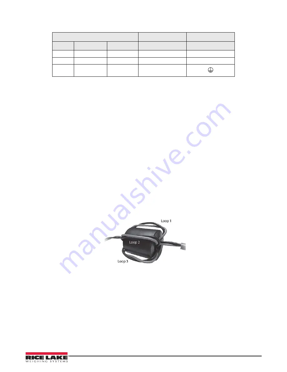
An EMI filter can be installed on the serial interface cable to eliminate RF interference (if necessary).
1. Run the serial wires through the EMI filter provided in the parts kit. See Table 2-3 on page 11.
2. Loop the serial wires around the EMI filter.
3. Use the provided plastic cable tie to secure the looped wires to the ferrite and the serial cable; this prevents
the ferrite from coming in contact with the CPU board.
Figure 2-4. Cylindrical Ferrite Placement for RF Interference
3-pin Terminal Block on Enclosure Back
To Power Supply
To Power Supply
Pin
Wire
Color
Pin
UL Approved Unit
1
Neutral
Blue or White
1
N
2
Hot
Brown or Black
2
L
3
Ground
Green or
Green/Yellow
Ground Tab
Table 2-1. AC Wiring Connections
Summary of Contents for LaserLight 2 Series
Page 36: ......


