13
The appliance and its individual gas shut-off valve must be
disconnected from the supply piping when pressure testing
the gas supply piping at pressures above ½ PSI
Table 8: Gas Pressures at Inlet to Appliance
PROPANE
NATURAL
GAS
Minimum (inches W.C.)
11
3
Maximum (inches W.C.)
11
14
*Recommended regulator settings is 7.0” w.c.
The gas supply line must be of adequate size to prevent
undue pressure drop and must never be smaller than the
size of the connection on the appliance. Sizing based on
Table 8 is recommended, depending on model.
Before operating the appliance, the complete gas train and
all connections must be tested using soap solution.
Verify that the appliance is supplied with the type of gas
specified on the rating plate. Heating values of local natural
gas are to be between 950 and 1010 Btu/ft
3
. Consult factory
if heating values are outside this range or if a gas with a
mixture of constituents is being used.
3.4
CHECKING GAS SUPPLY PRESSURE
•
Turn the main power switch to “OFF” position.
•
Shut off gas supply at the manual gas cock in the gas
piping to the appliance. If fuel supply is LP gas, shut off
gas supply at the tank.
•
Remove the 1/8" hex plug from the gas pressure test
port located on the inlet gas supply connection at the
rear of the appliance. Install a fitting in the inlet
pressure tapping suitable to connect to a manometer
or magnahelic gauge. Range of scale should be 0 to
14 inch W.C. or greater to check inlet pressure
•
Turn on gas supply at the field installed manual gas
cock; turn on LP gas at tank if required.
•
Turn the power switch to “ON” position.
•
Adjust the thermostat set point to call for heat.
•
Observe the gas supply pressure as the burner fires at
100% of rated input. Supply pressure is to remain
stable.
•
Ensure inlet pressure is within specified range.
Minimum and maximum gas supply pressures are
specified in Table 8.
•
If gas pressure is out of range, contact the gas utility,
gas supplier, qualified installer or service agency to
determine necessary steps to provide proper gas
pressure to the control.
•
If gas supply pressure is within normal range, proceed
to remove gas manometer and replace pressure tap
fittings in the gas piping to the appliance. Turn the
power switch to “OFF” position.
•
Turn on gas supply at the manual valve; turn on LP
gas at tank if required.
•
Turn the power switch to “ON” position.
•
Adjust the thermostat temperature set point to the
desired water temperature so the appliance will call for
heat.
•
Check appliance performance by cycling the system
while you observe burner response. The burner should
ignite promptly. Flame profile should be stable, see
section 10.2, Visually Check Main Burner Flames. Turn
system off and allow burner to cool, then cycle burner
again
to
ensure
proper
ignition
and
flame
characteristics.
IMPORTANT
Upon completion of initial installation or following any repair
work on the gas system, leak test all gas connections with a
soap solution while the main burner is firing. Immediately
repair any leak found in the gas train or related components.
DO NOT operate an appliance with a leak in the gas train,
valves or related gas piping.
3.5
HIGH and LOW GAS PRESSURE SWITCHES
(Optional)
High and low gas pressure switches are available as an
option and are wired in series with the blocked flue switch.
The high gas pressure switch is used to monitor the
differential gas pressure between the outlet of the control
valve and the fan inlet. If differential gas pressure exceeds the
maximum setting of the pressure switch, the appliance will
shut down and a low air condition will be indicated on the
display panel. The low gas pressure switch is to monitor the
minimum incoming gas supply pressure supplied to the gas
train. If gas pressure falls below the minimum setting of the
pressure switch, the appliance will shut down and a low air
condition will be displayed on the display panel.
3.6
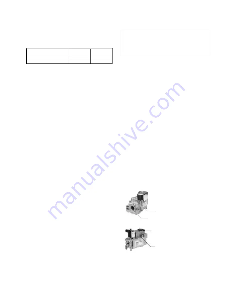
AIR/GAS RATIO VALVE
The main gas valve supplying gas to the burner on this
appliance utilizes a servo pressure regulator providing a slow
opening, fast closing safety shut off and air/gas ratio control
for the gas combustion process. The valve is a 1:1 negative
pressure gas valve. The valve performs the functions of a
pressure regulator, safety shutoff, and air/gas ratio control.
Full closing of the valve seat occurs in less than 0.8 seconds
when the valve is de-energized. Operation of the gas valve in
combination with the combustion air fan allows the burner
input rate to vary from 20% to 100% based on temperature
demand. The inlet gas supply pressure must be maintained
within the specified minimum and maximum pressures.
The air/gas ratio is preset at the factory and adjustment is not
usually required if gas supply pressure is maintained within
the specified range.
There are no serviceable parts on the air/gas ratio valve
control.
Figure 12: TH 82 – 252 1:1 Air/Gas Ratio Control Valve
Figure 13: TH 292 – 392 1:1 Air/Gas Ratio Control Valve
High fire adjustment:
use throttle screw
located on venturi
Low fire adjustment
screw Torx 40m
clockwise increases CO
2
Gas Inlet
Low-fire air gas ratio adjustment
(use Torx 40 for adjustment,
clockwise increases CO
2
)
High-fire air gas ratio adjustment (Use
slotted screwdriver for adjustment,
counter-clockwise increases CO
2
)


