41
10.3 CLEANING BOILER HEAT EXCHANGER
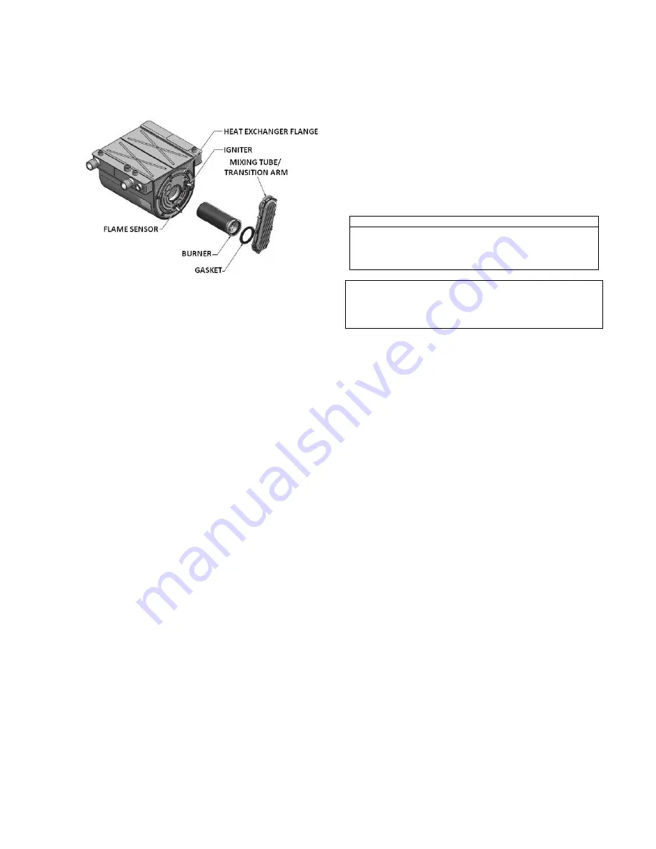
Figure 35: Heat Exchanger & Burner Assembly
1) Shut down boiler:
a) Turn the main power off to the boiler
b) Shut off gas supply at the main manual valve in
the gas piping of the main appliance
c) DO NOT drain the boiler unless it will be exposed
to freezing temperatures. If using antifreeze
prevention fluid in the heat exchanger, DO NOT
drain.
2) Allow time for the boiler to cool to room temperature if it
has been firing.
3) Remove the upper sheetmetal jacket.
4) Remove igniter and flame sensor electrodes. If
necessary, clean with steel wool. DO NOT use
sandpaper.
5) Remove the fan/ mixing tube assembly from the heat
exchanger door.
6) Remove burner.
7) Examine burner and clean if required as per 10.7.1.
8) Examine heat exchanger surfaces to determine if
cleaning is required. If cleaning is required remove the
(6) nuts fastening the heat exchanger flange from the
heat exchanger.
9) Disconnect the condensate hose from the heat
exchanger and connect a 5/8” diameter hose (field
supplied) from the bottom of the heat exchanger to a
drain
10) Use water proof material to carefully cover the refractory
at the rear of the combustion chamber of the heat
exchanger
11) Use a vacuum cleaner to remove any debris that has
collected on the heat exchanger surfaces. DO NOT use
any type of solvent.
12) Brush the heat exchanger with a nylon bristle brush. DO
NOT use a metal brush. Re-vacuum the heat
exchanger.
13) Finish cleaning by wiping down the boiler heating
surfaces with a clean, damp cloth.
14) Rinse out any additional debris with a low pressure
water supply. Start rinsing from the rear of the heat
exchanger and slowly working your way towards the
front of the heat exchanger.
15) Remove the water proof material after cleaning is
complete.
16) Re-install the heat exchanger door by evenly torquing
down the (6) nuts to 3 ft-lbs, burner, igniter and flame
sensor, and fan/ mixing tube assembly. Fasten the nuts
back to the heat exchanger assembly.
17) Re-connect the fan assembly to the boiler mixing tube.
18) Re-connect the condensate hose to the heat exchanger.
NOTE
All gaskets on disassembled components must be replaced
with new gaskets/sealant on re-assembly, if required. Gasket
kits are available from the factory
CAUTION
When the vent system is disconnected for any reason it must
be
reassembled
and
resealed
according
to
vent
manufacturer’s instruction
10.4
CONDENSATE TREATMENT
Condensate occurs when the products of combustion are
cooled below their dew point in the heat transfer process.
The liquid condensate formed from this high efficiency heat
transfer process is mildly acidic. The condensate will
typically have a pH ranging from 4.0 to 5.0 as it is
discharged from the condensate drain of the appliance. The
condensate collection box where the condensate is collected
is constructed of a non-corrosive plastic. All materials
external to the appliance in contact with the condensate
must be corrosion resistant. Condensate must be able to
flow freely from the appliance. All condensate flow is
accomplished by gravity requiring a minimum downward
slope of 1/4” per foot (21mm/m) to ensure proper flow to a
suitable drain. A neutralizer box is mounted inside each TH.
All condensate piping and connections must be easily
accessible for routine maintenance and inspection. Use solid
piping when running condensate line across the floor. Check
neutralized pH level regularly or as required by local
jurisdiction. Replace neutralizer medium as required.
10.4.1
Condensate Volume
There are several factors affecting amount of condensation
created by the appliance, however for rough approximation
use.
Condensation Volume, US Gallon/Hr = Input, MBH/1000 x
5.0
Many codes will require the acidic condensate to be
neutralized before it can be placed in a drain system. A
neutralizer to control the pH of the liquid discharged to a
drain system is provided with every TH boiler. The
neutralizer consists of an industrial grade, non-corrosive
plastic reservoir for collection of the condensate. The
condensate collects in the reservoir where it is in direct
contact with calcium carbonate neutralizer medium. As the
reservoir fills, it provides an extended residence time to
neutralize the condensate. Residency time in the neutralizer
reservoir allows time for the pH to be raised. Prime the
neutralizer reservoir with 1 litre of water.


