16
Table 10: Flow and Pressure Drop at a Given
Temperature Rise (DHW)
Input,
Btu/Hr
20 °F (11.1 °C)
Temp Rise
USGPM
(min.
flow)
∆∆∆∆
P Ft.
80,000
7.5
11.5
100,000
9.4
26.9
150,000
14.0
27.8
199,000
19.2
25.9
250,000
23.5
28.3
299,000
28.8
25.8
399,000
38.4
23.9
500,000
48.6
29.4
4.6
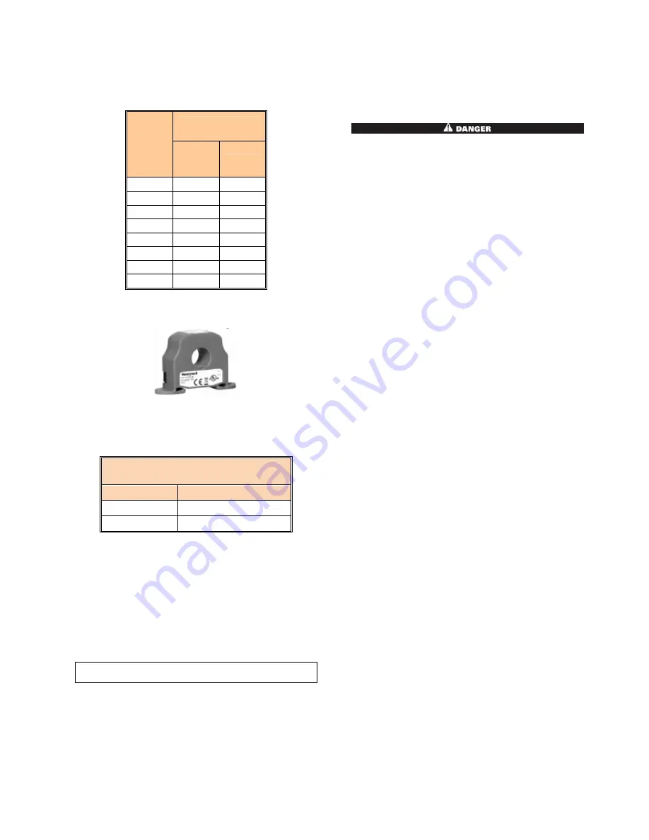
FLOW PROVING DEVICE
Figure 16: Flow Proving Device
The flow proving device is designed to detect when flow is
present. This is done by detecting the amount of current
(amperes) that exists in the live wire to the pump. When
the current becomes too low a flow switch error is displayed
indicating a lack of water flow inside the boiler.
Wall Mount
LED Illuminated
Symptom
TRIP ON
Normal operation
TRIP OFF
Current under trip point
4.7
T&P RELIEF VALVE
This appliance is supplied with a T&P relief valve sized in
accordance with ASME Boiler and Pressure Vessel Code,
Section IV. To prevent water damage, the discharge from
the relief valve shall be piped to a suitable floor drain for
disposal when relief occurs. No reducing couplings or other
restrictions shall be installed in the discharge line. The
discharge line shall allow complete drainage of the valve
and line. Relief valves should be manually operated at least
once a year.
CAUTION
Avoid contact with hot discharge water
4.8
STAINLESS STEEL STORAGE TANK
The TH is equipped with a stainless steel storage tank. A
20 gallon tank is supplied with TH Models 082 – 152, and a
40 gallon tank is supplied with TH Models 202 – 502. The
storage tanks are CSA certified and are rated to operate at
a maximum working pressure of 160 psig.
PART 5
ELECTRICAL &
CONTROLS
IT IS EXTREMELY IMPORTANT THAT THIS UNIT BE
PROPERLY GROUNDED!
5.1
ELECTRICAL CONECTIONS
Minimum 120VAC 60Hz single phase (15A circuit) is required
for the TH models TH-082 through TH-502. The appliance,
when installed, must be electrically grounded in accordance
with the requirements of the authority having jurisdiction or in
the absence of such requirements, with the latest edition of
the National Electrical Code ANSI/NFPA No. 70. When the
unit is installed in Canada, it must conform to the Canadian
Electrical Code, C22.1, Part 1 and/or local Electrical Codes.
•
All wiring between the appliance and field installed
devices shall be made with wire having minimum 220ºF
(105ºC) rating.
•
Line voltage wire exterior to the appliance must be
enclosed in approved conduit or approved metal clad
cable.
•
The pump must run continuously when appliance is being
fired.
•
To avoid serious damage, DO NOT ENERGIZE the
appliance until the system is full of water. Ensure that all
air is removed from the pump housing and piping before
beginning initial operation. Serious damage may result if
the appliance is operated without proper flow.
•
Provide the appliance with proper overload protection.
5.2
HIGH LIMIT
A manual reset fail-safe high limit aqua-stat control is internal
to the TH controller and the control bulb is installed in a dry
well in the heat exchanger outlet. The setting of this control
limits maximum discharge water temperature to 210
o
F. The
temperature of the outlet water in the heat exchanger must
drop a minimum of 5°F (2.7°C) below the setting of the high
limit control before the reset function can be activated.
5.3
TH CONTROLLER
This appliance uses a direct spark ignition control system.
The operation of the TH Controller for the direct spark igniter
proves the presence of main flame using a flame sensor proof
current (0.8µA). A status point alarm of Flame Fail will be
displayed on the main panel if the boiler fails to light after
three (3) ignition attempts.


