


F-1
Appendix F.
Thermistor Information
F.1 Converting Resistance to Temperature
The CDM-VW300 outputs a resistance value for sensors that contain a thermistor.
Temperature is normally calculated by applying the resistance to the Steinhart-
Hart equation, which converts resistance to temperature.
The Steinhart-Hart equation for converting resistance to degree Celsius is as
follows:
Temperature = 1/(A + B • LN(resistance) + C • (LN(resistance))^3) - 273.15
Where
A
,
B
, and
C
are coefficients for the Steinhart-Hart equation.
The coefficients for the Steinhart-Hart equation are specific to the thermistor
contained in your sensor and are obtained from the sensor manufacturer.
Please contact the sensor manufacturer to get coefficients for a
specific thermistor.
F.1.1 Resistance Conversion Example
– Geokon Sensor
If the coefficients for the Steinhart-Hart equation are as follows
A
= 1.4051E–03
B
= 2.369E–04
C
= 1.019E–07
The equation for converting the resistance measurement to degrees Celsius is:
Temperature = 1/(1.4051E–03 + 2.369E–04 • LN(resistance) +
1.019E–07 • (LN(resistance))^3) – 273.15
If the measured resistance is 2221 Ω, the calculated temperature in degree Celsius
is:
Temperature = 1/(1.4051E–03 + 2.369E–04 • LN(2221) +
1.019E–07 • (LN(2221))^3) – 273.15
Temperature = 31.98°C
F.2 Accuracy and Resolution
The accuracy of the temperature measurement is a function of the following
factors:
1. Thermistor interchangeability
2. Resistance of the wire
3. Steinhart-Hart equation error
4. Precision of the bridge resistors
NOTE
Summary of Contents for CDM-VW300 Series
Page 2: ......
Page 4: ......
Page 6: ......
Page 12: ......
Page 59: ...User Manual 47 Figure 7 16 LoggerNet connect screens showing frequencies from CDM VW300 ...
Page 70: ...CDM VW300 Series Dynamic Vibrating Wire Analyzers 58 ...
Page 76: ...Appendix B SC CPI Datalogger to CPI Interface B 4 ...
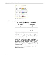
Page 80: ...Appendix C CDM Devices and CPI Bus C 4 Figure C 2 Long cable lengths of a distributed CPI bus ...
Page 86: ...Appendix E Calculating Measurement Error E 4 ...
Page 116: ...Appendix G CRBasic Program Library G 26 ...


