


User Manual
23
11.
Monitor the operation of the system.
Reference Section 7.12.2,
Monitoring System Performance
.
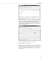
Using the datalogger support software, monitor the datalogger
Public
table as
indicated in the following figure. In the
Public
table, frequency data can be
displayed that correspond to the channels selected for measurement. The
following figure shows
Public
table variables
Freq(1)
,
Diag(1)
,
StaticFreq(1)
,
Therm(1)
,
DynStdDev(1)
as active with frequency data from
one sensor. The sensor is connected to channel
1
of the CDM-VW305.
A clean display of data, as shown in the previous figure, is obtained by
deactivating all but channel
1
in the CRBasic program. If channels
2
through
8
had not been deactivated, erroneous, but perhaps seemingly-real, data would be
displayed. Channels
2
through
8
are deactivated by setting line 24 in the CRBasic
example in Appendix G.1.2,
20 Hz Measurement Example – One CDM-VW305,
Eight Channels
, to the following:
Dim
Enable(8)
As Long =
{ 1, 0, 0, 0, 0, 0, 0, 0}
If proper frequencies are shown, the datalogger has successfully communicated
with the CDM-VW300 via the SC-CPI device and obtained data. A permanent
data collection program for field operation can now be loaded.
7.
System Operation
IMPORTANT — Do not connect the CDM-VW300 analyzer or SC-CPI interface
to a PC until AFTER installing
DVWTool
1.0 or later or
DevConfig
2.04 or later.
Consult Section 7.1.1,
Software and Driver Installation,
for more information.
7.1
PC Based Tools
All PC software is for use on
Windows
®
XP
,
Windows
®
Vista
,
Windows
®
7
, or
Windows
®
8
operating systems.
7.1.1
Software and Driver Installation
USB communication between the PC and the CDM-VW300 analyzer, and
between the PC and the SC-CPI interface, require that USB drivers be installed on
the PC. For driver installation to work seamlessly, the drivers must be installed
before making the physical USB connections. These drivers are installed
automatically when
DVWTool
1.0 software or
DevConfig
2.04 software or later
are installed.
Summary of Contents for CDM-VW300 Series
Page 2: ......
Page 4: ......
Page 6: ......
Page 12: ......
Page 59: ...User Manual 47 Figure 7 16 LoggerNet connect screens showing frequencies from CDM VW300 ...
Page 70: ...CDM VW300 Series Dynamic Vibrating Wire Analyzers 58 ...
Page 76: ...Appendix B SC CPI Datalogger to CPI Interface B 4 ...
Page 80: ...Appendix C CDM Devices and CPI Bus C 4 Figure C 2 Long cable lengths of a distributed CPI bus ...
Page 86: ...Appendix E Calculating Measurement Error E 4 ...
Page 116: ...Appendix G CRBasic Program Library G 26 ...


