


CDM-VW300 Series Dynamic Vibrating-Wire Analyzers
16
a.
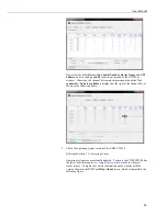
Frequency reading of each sensor will correspond to the frequency
range specified by the sensor manufacturer.
b.
No faults are indicated. If faults are indicated (
Diagnostic Bits
does
not equal
0x00
, measurement results are in red type, or cells are
shaded red), consult Section 7.12.2.1,
Monitoring with DVWTool
Software
, for troubleshooting help.
6.2
Field-Mode Installation
IMPORTANT — Do not connect the CDM-VW300 analyzer or SC-CPI interface
to a PC until AFTER installing
DVWTool
1.0 or later or
DevConfig
2.04 or later.
Consult Section 7.1.1,
Software and Driver Installation,
for more information.
A simple field-mode configuration, using one CDM-VW300, is covered in this
section. Additional details concerning field-mode configuration and daisy-
chaining power and RJ45 connections are discussed in Section 7,
System
Operation
. Capacity of the power supply is a critical element of field
installations. Most field-mode installations will require continuous ac power or
large solar panels and batteries.
6.2.1
Field-Mode Installation Equipment
The following components are used in a field-mode installation:
Vibrating-wire sensors
CDM-VW300 measurement modules
SC-CPI interface
Datalogger
Datalogger power supply
Personal computer (PC)
DVWTool
analyzer software
Datalogger support software (
LoggerNet
,
PC400
, or
RTDAQ
)
6.2.2
Field-Mode Installation Procedure
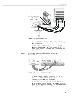
Figure 6-7 illustrates the final form of a simplified field-mode installation. With
reference to this figure, work through the following procedure. Reference Section
7.7,
System Connections
, for more information.
Summary of Contents for CDM-VW300 Series
Page 2: ......
Page 4: ......
Page 6: ......
Page 12: ......
Page 59: ...User Manual 47 Figure 7 16 LoggerNet connect screens showing frequencies from CDM VW300 ...
Page 70: ...CDM VW300 Series Dynamic Vibrating Wire Analyzers 58 ...
Page 76: ...Appendix B SC CPI Datalogger to CPI Interface B 4 ...
Page 80: ...Appendix C CDM Devices and CPI Bus C 4 Figure C 2 Long cable lengths of a distributed CPI bus ...
Page 86: ...Appendix E Calculating Measurement Error E 4 ...
Page 116: ...Appendix G CRBasic Program Library G 26 ...


