


CDM-VW300 Series Dynamic Vibrating-Wire Analyzers
20
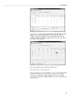
Figure 6-10. Connecting the CPI ports of the SC-CPI and CDM-VW300
c.
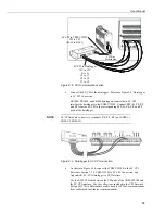
As shown in Figure 6-11, place a CPI terminator in the remaining open
CPI port of the CDM-VW300 unless more CDM-VW300 devices will be
daisy-chained.
Figure 6-11. Install CPI bus terminator
7.
As shown in Figure 6-12, connect power leads to the CDM-VW300. Do not
turn power on until the system is fully assembled.
Connect dc power to the
Power
connector on the side of the CDM-VW300.
Voltages from 10 to 32 Vdc may be used. Do not connect ac power directly
to the CDM-VW300. A convenient power source is the combination of
12V
and
G
terminals on the face of the datalogger.
Connect SC-CPI to CDM-VW300:
RJ-45 to RJ-45
Summary of Contents for CDM-VW300 Series
Page 2: ......
Page 4: ......
Page 6: ......
Page 12: ......
Page 59: ...User Manual 47 Figure 7 16 LoggerNet connect screens showing frequencies from CDM VW300 ...
Page 70: ...CDM VW300 Series Dynamic Vibrating Wire Analyzers 58 ...
Page 76: ...Appendix B SC CPI Datalogger to CPI Interface B 4 ...
Page 80: ...Appendix C CDM Devices and CPI Bus C 4 Figure C 2 Long cable lengths of a distributed CPI bus ...
Page 86: ...Appendix E Calculating Measurement Error E 4 ...
Page 116: ...Appendix G CRBasic Program Library G 26 ...


