


User Manual
11
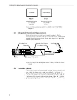
Reference Section 7.4,
Using Power Supplies
.
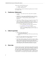
Campbell Scientific pn #29796, a 24 Vdc, 1670 mA wall charger, is
recommended.
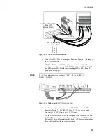
Figure 6-2. 12 Vdc power connection on the CDM-VW300
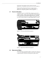
3.
Connect a type-A male to type-micro-B male USB cable (Campbell Scientific
pn #27555, supplied with the analyzer) between the CDM-VW300 and the PC
as shown in Figure 6-3.
Reference Section 7.7.1,
CDM-VW300 to PC Connection
.
Figure 6-3. USB receptacle on CDM-VW300 and Type-Micro-B connector
of USB cable
Leads from
pn #13947
transformer
Insert small
screwdriver
to open gates.
Summary of Contents for CDM-VW300 Series
Page 2: ......
Page 4: ......
Page 6: ......
Page 12: ......
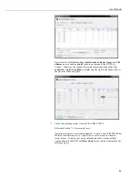
Page 59: ...User Manual 47 Figure 7 16 LoggerNet connect screens showing frequencies from CDM VW300 ...
Page 70: ...CDM VW300 Series Dynamic Vibrating Wire Analyzers 58 ...
Page 76: ...Appendix B SC CPI Datalogger to CPI Interface B 4 ...
Page 80: ...Appendix C CDM Devices and CPI Bus C 4 Figure C 2 Long cable lengths of a distributed CPI bus ...
Page 86: ...Appendix E Calculating Measurement Error E 4 ...
Page 116: ...Appendix G CRBasic Program Library G 26 ...


