


CDM-VW300 Series Dynamic Vibrating-Wire Analyzers
12
With the driver installed (step 1) and the power connected and live (step 2),
connecting the USB cable will start an automatic process that creates a new
communication (COM) port for the CDM-VW300 on the PC. Watch the
Windows
® system tray to see that the PC completes the process. Once
complete, a new port will appear as an available communication port in
DVWTool
.
4.
Test to see that
DVWTool
can access the USB connection.
Reference Section 7.1.2,
Using DVWTool
.
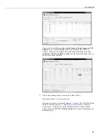
Run
DVWTool
. Select
CDM-VW300
from the
Com Port
drop-down list as
indicated in the following figure.
If COM port
CDM-VW300
does not appear, there is a problem with
the installation of the device driver or the creation of the COM port.
See Section 7.1.1,
Software and Driver Installation
, for remedial
steps.
Press
Connect
in the lower left of the
DVWTool
window. If
DVWTool
connects with the CDM-VW300, the channel list on the
DVWTool
interface
becomes available and the button at lower left reads
Disconnect
as shown in
the following figure.
NOTE
Summary of Contents for CDM-VW300 Series
Page 2: ......
Page 4: ......
Page 6: ......
Page 12: ......
Page 59: ...User Manual 47 Figure 7 16 LoggerNet connect screens showing frequencies from CDM VW300 ...
Page 70: ...CDM VW300 Series Dynamic Vibrating Wire Analyzers 58 ...
Page 76: ...Appendix B SC CPI Datalogger to CPI Interface B 4 ...
Page 80: ...Appendix C CDM Devices and CPI Bus C 4 Figure C 2 Long cable lengths of a distributed CPI bus ...
Page 86: ...Appendix E Calculating Measurement Error E 4 ...
Page 116: ...Appendix G CRBasic Program Library G 26 ...


