IB0147 Rev. 08
LEFM 200 Modbus User Manual
Section 3
Page 22
December 2010
Using the above coefficients, the transmitter does a linear scale:
Analog Input (engineering units) = Y1 +(Analog Input-X1)*(Y2-Y1)/(X2-X1)
For example, for a 100
RTD (-100 to 100°C), 0 volts represent -100°C and 5 volts represents
100°C.
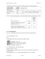
Holding Register Address
Variable Description
Name
Meter Body
Temp Input1
Pressure
Input 2
N/A
Input 3
N/A
Input 4
Minimum Voltage for Inputs
X1(j)
104
112
120
128
Minimum Engineering Value at
Minimum Voltage
Y1(j)
106
114
122
130
Maximum Voltage for Inputs
X2(j)
108
116
124
132
Maximum Engineering Value at
Maximum Voltage
Y2(j)
110
118
126
134
3.6
Analog Outputs
Output Scaling B1, A1, B2, A2
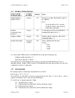
B1/B2 are in engineering units and A1/A2 are in counts (0 for minimum range, 65535 for
maximum range).
Analog Output (counts) = A1 +(analog engineering units-B1)*(A2-A1)/(B2-B1),
Default Outputs
Output 1 Flow,
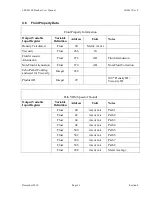
The following table defines addresses for the Analog Output setups. The variables are entered as
Floats, however, the counts values are limited to integers. The equation used is as follows:
Analog Output(i) (counts) = B1 +(Output(i)-A1)*(B2-B1)/(A2-A1)
Where:
65535 is full scale (i.e., 20 mA for a 4-20 mA output)
0 is minimum scale (i.e., 4 mA for a 4-20 mA output)
Holding Register Address
Variable Description
Name
Output1
Output 2
Output 3
Output 4
Minimum Engineering Value
A1(j)
136
144
152
160
Minimum Count Value
B1(j)
138
146
154
162
Maximum Engineering Value
A2(j)
140
148
156
164
Maximum Count Value
B2(j)
142
150
158
166
Summary of Contents for LEFM 200
Page 4: ...IB0147 Rev 08 LEFM 200 Modbus User Manual Table of Contents Page ii December 2010 ...
Page 22: ...IB0147 Rev 08 LEFM 200 Modbus User Manual Section 2 Page 18 December 2010 ...
Page 28: ...IB0147 Rev 08 LEFM 200 Modbus User Manual Section 3 Page 24 December 2010 ...
Page 40: ...IB0147 Rev 08 LEFM 200 Modbus User Manual Section 4 Page 36 December 2010 ...


