Chapter 5: Installation
237
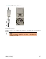
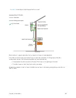
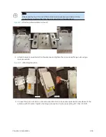
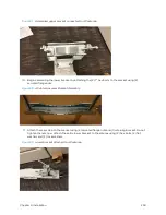
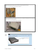
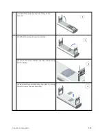
Figure 93 :
Connect the port A and B to the PMP 450i AP
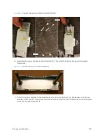
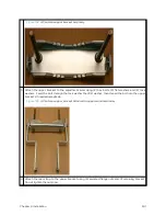
6. Assemble the upper bracket by attaching the (2) 7” hex bolts to the bracket using (2) serrated
flange nuts
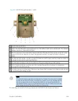
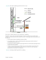
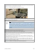
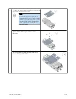
Figure 94 :
AP antenna upper bracket assembly
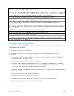
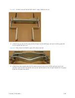
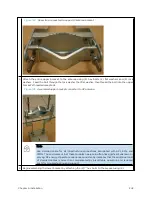
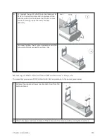
7. Attach the upper bracket to the adjustment arms using (2) hex bolts, (2) flat washers and (2) lock
washers. Feed the bolt through the lock washer then flat washer, then thread the bolt into the upper
bracket’s threaded receptacle.
Summary of Contents for PMP 450 Series
Page 92: ...Chapter 2 System hardware 92 Figure 29 MicroPoP Omni antenna implementation pattern Vertical...
Page 134: ...Chapter 3 System planning 134 Figure 51 Mast or tower installation...
Page 135: ...Chapter 3 System planning 135 Figure 52 Wall installation...
Page 136: ...Chapter 3 System planning 136 Figure 53 Roof installation...
Page 137: ...Chapter 3 System planning 137 Figure 54 GPS receiver wall installation...
Page 158: ...Chapter 3 System planning 158 Figure 61 cnMedusa Antenna...

