Chapter 5: Installation
208
7
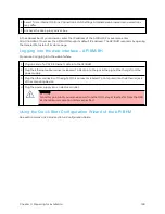
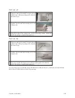
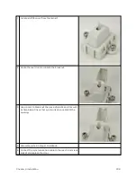
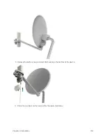
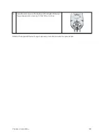
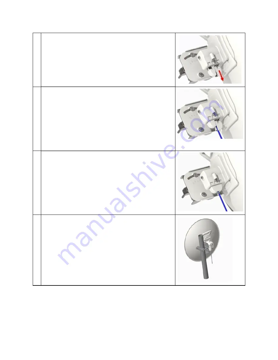
Unclip the door nearest the dish by squeezing at the two
thumb marks.
8
Connect the RJ45 connector to the radio and replace the door.
9
Use a tie wrap to secure the Ethernet cable to center post of the
cover.
10
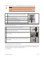
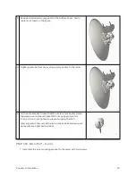
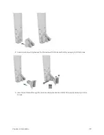
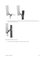
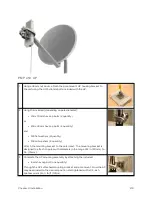
On the pole bracket, loosen the M8 nuts to remove outer clamp.
Slip clamp over pole and tighten M8 nuts by applying 8 Nm
torque. Do not over tighten to prevent aligning the dish.
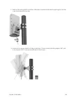
After alignment, ensure that the two bracket bolts and two pole
clamp nuts are tightened to 25 Nm.
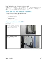
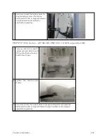
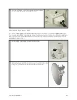
Fit t ing a synchronizat ion cable t o t he aux port
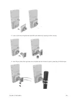
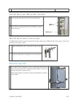
For PTP Backhaul Master applications requiring synchronization, a synchronization cable may be fitted to
the aux port as described below. Before installation of the 450b, prepare the cover as per the steps below:
Summary of Contents for PMP 450 Series
Page 92: ...Chapter 2 System hardware 92 Figure 29 MicroPoP Omni antenna implementation pattern Vertical...
Page 134: ...Chapter 3 System planning 134 Figure 51 Mast or tower installation...
Page 135: ...Chapter 3 System planning 135 Figure 52 Wall installation...
Page 136: ...Chapter 3 System planning 136 Figure 53 Roof installation...
Page 137: ...Chapter 3 System planning 137 Figure 54 GPS receiver wall installation...
Page 158: ...Chapter 3 System planning 158 Figure 61 cnMedusa Antenna...

