Chapter 2: System hardware
55
Note
SFP
kits
(Single
Mode
Optical
SFP
Interface
per
ODU
(part
number
C000065L008A), Multi- mode Optical SFP Interface per ODU (part number
C000065L009A), and 2.5GBASE-T Copper SFP Interface per ODU (part number
C000065L011A)) are required for SFP port connectivity.
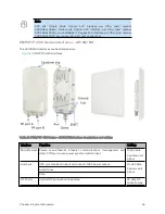
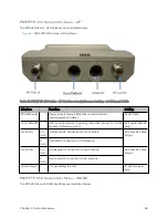
PMP/ PTP 4 50 i Series int erfaces – AP/ SM/ BH
The AP/SM/BH interfaces are illustrated below.
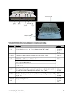
Figure 5 :
PMP/PTP 450i interfaces
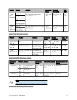
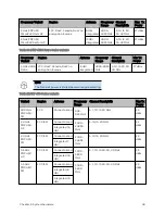
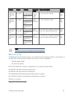
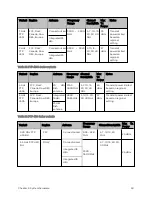
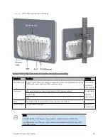
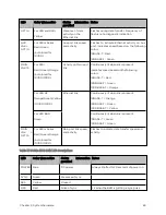
Table 28 :PMP/PTP 450i Series - AP/SM/BH interface descriptions and cabling
Interface
Function
Cabling
PSU/Ethernet
Power- over- Ethernet, Ethernet communications (management and
data), CMM sync-over-power synchronization input
RJ45 Cable
See Main port
pinout
Aux/Sync
GPS synchronization input and output, UGPS power output
RJ 45 Cable
See Aux port
pinout
Audio tones
Data
RF Port A
Vertical RF connection to antenna
50 ohm RF
cable, N-type
Summary of Contents for PMP 450 Series
Page 92: ...Chapter 2 System hardware 92 Figure 29 MicroPoP Omni antenna implementation pattern Vertical...
Page 134: ...Chapter 3 System planning 134 Figure 51 Mast or tower installation...
Page 135: ...Chapter 3 System planning 135 Figure 52 Wall installation...
Page 136: ...Chapter 3 System planning 136 Figure 53 Roof installation...
Page 137: ...Chapter 3 System planning 137 Figure 54 GPS receiver wall installation...
Page 158: ...Chapter 3 System planning 158 Figure 61 cnMedusa Antenna...

