background image

18 HYDRA2


Operator Manual

Introduction - Hydra2 Networking

I/O BOX IDENTIFICATION

Each I/O box on the Hydra2 network 
needs to be given a unique ID in the 
form of a number between 0 and 255. 
The Hydra ID, or “HID” for each box 
is set using a DIP switch accessible 
from the rear of fixed format I/O 
boxes, or on the side of the controller 
card within a modular I/O box. 

Label pockets are fitted to the front panel 
of I/O boxes to aid visual identification.

FixedFormatI/Oboxes

The 8 way DIP switch is set as an 8 bit 
binary representation of the HID value 
with the left hand switch used for the 
most significant bit, and the right hand 
switch for the least significant bit. A switch 
in the down / off position represents 
a binary 0 and a switch set in the up / 
on position represents a binary 1. Each 
switch / binary bit equates to a decimal 
value, starting at 1 for the least significant 
bit. The remaining switches are double 
the value of their less significant neighbor, 
making the 8th / most significant bit 
equate to a decimal value of 128.

All fixed format I/O box ID switches are 
orientated the same way, though some 
boxes, such as MADI units, use a different 
style switch with more pronounced 
labelling. Ignore any labels on the switch 
itself and always refer to the Calrec  
labelling on the surrounding panel which 
will show the most significant bit switch on 
the left and the binary 1 position as up.

Care should be taken when setting HIDs 
to avoid accidentally duplicating the same 
ID on more than one box. Duplicate box 
IDs can cause network conflicts. I/O 
boxes should be disconnected from the 
network before changing their HID, and 
reset or power cycled once the DIP switch 
is set to ensure the new HID is active 
before reconnecting to the network.

If replacing an I/O box for any reason, 
choosing a box of the same type as the 
original and setting it with the same ID 
makes it a drop-in replacement which will 
work with existing user memories and  
settings, requiring no further configuration.

When connecting additional I/O boxes to 
a network it is important to be aware of 
the existing I/O HIDs in order to select 
a unique number and avoid creating a 
conflict.

Address2

Some I/O boxes, such as MADI units, 
are fitted with 2 banks of DIP switches—
Address 1 and Address 2—to provide 
a 16 bit ID, and therefore a greater 
range of values. Please note that only ID 
values between 0 and 255 are currently 
supported. Any DIP switches labelled 
Address 2 should all be set to the off 
position.

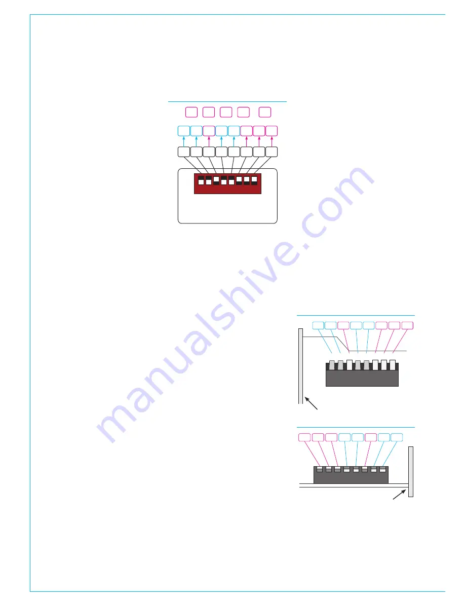
ModularI/OboxIDsetting

The ID for modular I/O boxes is set by 
a DIP switch on the controller card and 
is only accessible by removing the card. 
Please refer to the Hydra2 installation 
manual and ensure ESD precautions are 
observed before removing any modular 
I/O box cards.

ID switches on modular I/O controller 
cards are orientated differently. Ignore any 
labelling on the switch itself and refer to 
the Calrec labelling printed on the circuit 
board around the switch to clarify its 
orientation. When viewing the card from 
the side, the most significant bit is on the 
left and the least significant bit on the 
right. Pulling a switch towards you sets it 
as a binary 1, away from you as a binary 
0. The following illustrations show the 
ID switch on the modular I/O controller 
card from the side and top views. Again 
the decimal value of 39 is used for the 
example.

1

1 0

2

3

4

5

6

7

ADDRESS

0

1

0

0

0

1

0

0

1

1

1

128 64 32 16 8

4

2

1

32

4

2

1 =

+

+

+

39

STANDARD SWITCH FOR HID SETTING

•  The above diagram shows how 

each switch relates to a decimal 
value. The setting shown in the 
example provides a decimal 
HID value of 39

MODULAR I/O CONTROLLER - SIDE 

0

1

2

3

4

5

6

7

ID BITS

Sw3

1

2

4

8

16

32

64

128

Front Panel

1

2 4 8 16 32 64 128

MODULAR I/O - VIEWED FROM TOP 

Front Panel

Summary of Contents for Hydra2

Page 1: ...calrec com Putting Sound in the Picture HYDRA2 ORGANIZER USER GUIDE Gigabit Ethernet Networking H2O...

Page 2: ...on is for International usage Calrec Audio Ltd reserve the right to change specifications without notice E O E The established policy of Calrec Audio Ltd is to seek improvements to the design specific...

Page 3: ...0 21 Connection and Login 22 Connection 22 Accessing H2O 22 I O Boxes and Port Labels 23 Add Remove I O boxes 23 Box and Port Labels 23 Access Rights 25 Manage Folders 26 Organizing Folders 26 Adding...

Page 4: ...4 HYDRA2 Operator Manuel...

Page 5: ...calrec com Putting Sound in the Picture H2O INFORMATION...

Page 6: ...ditions A copy of this is available on request Repairs If you need to return goods to Calrec for whatever reason please contact your regional distributor or Calrec customer support beforehand for guid...

Page 7: ...ing individual boards and modules many highly static sensitive parts are exposed In order to protect these devices from damage and to protect your warranty please observe static handling procedures fo...

Page 8: ...60320 1 C13 C14 couplers Do not allow ventilation slots to be blocked Do not leave the equipment powered up with the dust cover fitted Cleaning For cleaning the front panels of the equipment we recom...

Page 9: ...calrec com Putting Sound in the Picture H2O INTRODUCTION HYDRA2 NETWORKING...

Page 10: ...ts and the switching capability Each connection between Hydra2 units can carry up to 512 signals in both directions simultaneously at 48kHz I O interfaces are available in a range of format types incl...

Page 11: ...can also be sent to multiple output ports I O boxes and be made available to other consoles via Hydra Patchbays SINGLE CONSOLE NETWORKS Input to output patching provides routing capability without th...

Page 12: ...irect or via the other processing rack Removing any one of the three marked links will correct the problem When connecting two or more routers together it is important that one of them and only one is...

Page 13: ...48V SIG 1L 48V SIG 1R 48V SIG 2L 48V SIG 2R 48V SIG 3L 48V SIG 3R 48V SIG 4L 48V SIG 4R 1L 48V SIG 5L 1R 48V SIG 5R 2L 48V SIG 6L 2R 48V SIG 6R SIG SIG SIG SIG RESET R Y H D A AN LOG A 12 4 INPUTS OU...

Page 14: ...tive and that any console that is powered on has access to all their own I O as well as all I O connected to the Router Core Audio I O Router Core Console Core Audio I O Audio I O Audio I O Audio I O...

Page 15: ...gure 1 Confirming IPs To confirm the IP addresses associated with a processing rack log in with administrator privileges to the PC associated with that rack and launch the Calrec Program Updater appli...

Page 16: ...gy to know which I O boxes are available to which consoles if individual racks other than the Master are powered down When two or more networks are joined or a network is split for example if two OB m...

Page 17: ...SOR 1 PROCESSOR 2 DSP 2 PSU 1 PSU 2 CONTROL EXPANSION 1 ROUTER 1 hydra EXPANSION 2 ROUTER 2 hydra MOK ST0 ST1 ST2 ST3 ST4 ST5 ST6 AC IN USB ST1 ST2 ST3 ST4 ST5 ST6 AC IN USB MOK ST0 ROUTER EXPANDER PS...

Page 18: ...any reason choosing a box of the same type as the original and setting it with the same ID makes it a drop in replacement which will work with existing user memories and settings requiring no further...

Page 19: ...scheme as external I O cards are never fitted in this location It is instead labelled H2 Interface and is always populated with a Hydra2 network interface card A source list port label of 12 K 04 wou...

Page 20: ...20 HYDRA2 Operator Manuel...

Page 21: ...calrec com Putting Sound in the Picture H2O USING H20...

Page 22: ...PROCESSOR 1 PROCESSOR 2 DSP 2 PSU 1 PSU 2 CONTROL EXPANSION 1 ROUTER 1 hydra EXPANSION 2 ROUTER 2 hydra MOK ST0 ST1 ST2 ST3 ST4 ST5 ST6 AC IN USB ST1 ST2 ST3 ST4 ST5 ST6 AC IN USB MOK ST0 ROUTER EXPA...

Page 23: ...can be used to add I O to the database when the physical I O box is not available This allows for setup and pre configuration of future expansion to the network The Boxes function can be used to remov...

Page 24: ...n edited from the default values on the console PC itself in which case the local custom labels take precedence Note up to 20 characters can be entered as port labels All 20 characters are visible in...

Page 25: ...ates the whole folder is restricted A half blue background indicates that the folder contains a mixture of ports that can and cannot be accessed If a port appears in more than one folder removing acce...

Page 26: ...ts to be selected on an individual basis if required The FOLDERS button can be used to remove folders that are no longer needed and the FOLDERS EDIT button can be used to re label folders if required...

Page 27: ...port being restricted Port Grouping Port lists are sorted alphabetically which will not always place related ports together For example it can be convenient to have a 5 1 set of signals which are desi...

Page 28: ...type and number needs to be entered The type should be set as Apollo Artemis Summa for consoles or Router for a standalone rack Each system has to be given a unique label e g Studio1 The Number field...

Page 29: ...o show the folder path Clicking the folder labels in the navigation bar takes the screen back to view those folders Alternatively clicking the tree structure button at the bottom of the window changes...

Page 30: ...rce settings The first picture on this page shows accessible settings for Mic Line I O boxes To enable source settings for any port simply check the checkbox Selecting the gain control displays a leve...

Page 31: ...than one patching conflict In such cases the table will have several rows From H2O it is also possible to un patch ports from desk connections Note that H2O un patches are not held in console hidden m...

Page 32: ...op up the current salvo can be saved by clicking SAVE SALVO At this point you can either create a new salvo or overwrite a previously created one by clicking on its name in the list When creating a ne...

Page 33: ...selected sync sources to be changed and reset if required Changes made to a console s sync settings in H2O are instantly reflected on the console s PC Touch Display interface H2O does not have priori...

Page 34: ...ion The Files and buttons at the bottom of the screen allow for files to be added and removed from the list As well as inserting metadata into SDI outputs EMBER controllers can selectively mute any of...

Page 35: ...ole inputs and outputs which have been patched to Hydra Patchbay ports to physical I O ports H2O users can choose physical input ports to connect to console s Hydra Patchbay inputs and physical output...

Page 36: ...irectly affect other network users Console operators are given the ability to change the source feeding a HPB that is feeding other consoles to add increased flexibility However we advise that all I O...

Page 37: ...process by closing H2O or resetting the Master Control processor A confirmation message is displayed upon completion Editing CSV files CSV files can be manually edited Using spreadsheet software to vi...

Page 38: ...es when a source that is unknown to the 3rd party device is patched to a destination These values are entered from the Control Protocols IO BOX PORT LABELS SW P 08 MAPPING SCREEN CONTROL PROTOCOLS SCR...

Page 39: ...CALREC Putting Sound in the Picture 39...

Page 40: ...926 166 Iss 10 Calrec Audio Ltd Nutclough Mill Hebden Bridge West Yorkshire England UK HX7 8EZ Tel 44 0 1422 842159 Fax 44 0 1422 845244 Email Enquiries calrec com calrec com...

Reviews: