background image

12   |   

P a g e


Cleaning   the   UV   Sensor   (if   applicable)   

Depending   on   the   water   quality,   the   UV   sensor   may   require   periodic   cleaning.   At   a   minimum,   the   UV   sensor   should   
be   cleaning   on   an   annual   basis.   The   following   steps   outline   a   basic   cleaning   procedure.   

Step   1:    If   the   system   has   an   inlet   shut-­‐off   valve,   shut   this   valve   off   to   prevent   water   flow   through   the   system.   If   
there   is   no   inlet   shut-­‐off   valve,   turn   off   main   water   inlet   valve   (and   turn   of   water   pump   if   you   have   one).   

Step   2:    Disconnect   the   power   cord   of   the   UV   system   from   the   electrical   outlet.   

Step   3:    Release   water   pressure   by   opening   a   downstream   tap   and   close   the   outlet   shut-­‐off   valve   if   the   installation   
incudes    one    (if    there    is    no    outlet    shut-­‐off    valve,    be    prepared    for    water    leakage    from    the    system    as    the    head   
pressure   in   the   system   will   cause   water   to   flow   back   through   the   outlet   plumbing   and   through   the   unit).   

Step   4:    Place   a   container   under   the   unit   to   catch   any   water   that   may   come   out   of   the   unit   during   the   removal   of   
the   UV   sensor.   

Step   5:      Unscrew   (counterclockwise)   the   sensor   nut   from   the   unit   and   pull   the   sensor   slowly   out   of   the   sensor   port.   

Step   6:    Holding   the   sensor   in   your   hand   wipe   the   flat   portion   (sensor   face)   of   the   sensor   with   isopropyl   alcohol   
using   a   clean   lint-­‐free   cloth.   

Step   7:      Replace   sensor   as   per   instructions   on   pages   8-­‐9   of   the   manual.   


Operation   

The   CALMAG   YORKSHIRE   LIMITED   system   comes   with   a   feature   laden   controller   that   incorporates   both   the   lamp   

driver   (ballast)   and   control   features   in   one   water-­‐tight   case.   CAUTION:   Prior   to   performing   any   maintenance   on   

your   UV   system,   you   must   always   disconnect   the   power.   


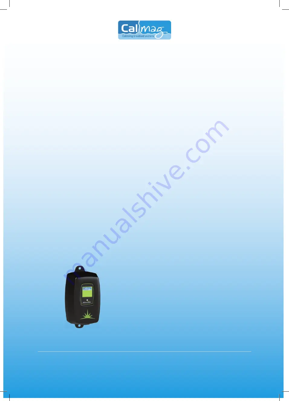
CALULTRA   DOMESTIC   CONTROLLER   

This   controller   features   a   power   factor   corrected,   constant   current   lamp   
driver   with   a   universal   power   input.   A   full   colour   LCD   screen   provides   the   
user   with   a   detailed   description   of   the   system’s   performance   in   addition   
to    providing    any    applicable    fault    messages    and    system    diagnostics.    All   
controllers    include    an    “infinite    expandability    port”    located    on    the    right   
side   of   the   controller.   Simply   plug   in   an   optional   UV   sensor   module   into   
the   expandability   port   of   the   controller   and   the   system   will   now   monitor   
the    UV    intensity    of    the    system.    Please    call    for    details,    price    and   
availability.   


Summary of Contents for CALULTRA 12

Page 1: ...Remember don t guess ASK Calming troubled waters...

Page 2: ...ter supply with a UV system gives you reassurance that your family will have access to safe drinking water throughout your entire home with no chance of microbiological contamination This is chemical...

Page 3: ...on Controller Overview Page 12 Operation Power up Sequence Page 13 Operation Remote Alarm Module Check Page 14 Operation Operational Screens Page 14 Operation UV Intensity Page 15 Operation Lamp Count...

Page 4: ...ed to be installed indoors and away from leaking plumbing DO NOT plug the unit in if the system or any of the components are wet 9 The disinfection system should be directly installed into a ground fa...

Page 5: ...mendations You can have your water tested at a private analytical laboratory or contact your local council for advice in regards to your local environmental health officer It is always recommended to...

Page 6: ...litres per minute it is recommended to install the CALULTRA 79 UV unit There will be occasions where your home is using water at the pump s maximum capacity Location Step 1 Find a suitable location t...

Page 7: ...or so that the rated flow of your particular CALMAG YORKSHIRE LIMITED system is not exceeded and the UV dose is not compromised The flow restrictor should be installed on the outlet port of the unit S...

Page 8: ...P a g e Installation example unit connect ASSEMBLED ring installation unit unit ring unit unit...

Page 9: ...ly and check for leaks Make sure the by pass valves are functioning properly and that the water is flowing through the unit The most common leak is from the O ring not making a proper seal on the unit...

Page 10: ...d Screw Connection Step 17 Your system is now ready to be plugged into the appropriate GFCI protected outlet Plug the unit in and refer to the System Disinfection section before any water is allowed t...

Page 11: ...inlet shut off valve shut this valve off to prevent water flow through the system If there is no inlet shut off valve turn off main water inlet valve and turn of water pump if you have one Step 2 Disc...

Page 12: ...rew counterclockwise the sensor nut from the unit and pull the sensor slowly out of the sensor port Step 6 Holding the sensor in your hand wipe the flat portion sensor face of the sensor with isopropy...

Page 13: ...at the end of 12 months to replace the ultra violet bulb The Calmag Home Screen will then constantly scroll from right to left indicating that the unit is functioning correctly If the controller butt...

Page 14: ...the front of the controller UV Intensity only for units equipped with a UV sensor If your system is equipped with a UV sensor the UV Output screens will indicate the level of UV intensity that is bei...

Page 15: ...he flow of water if a solenoid valve is installed on the system Lamp Countdown Sequence The UV unit counts down the number of days until a lamp change is required The operation is as follows Once the...

Page 16: ...lamp To perform this reset you must firmly depress the button on the front of the controller and then manually plug the power cord back into the wall outlet initiating power to the unit Keep holding...

Page 17: ...Assuming the system has an optional 4 20 mA Module installed if at any time during the operation of the system a 4 20 mA module fails the controller will return both an audible and visual signal indi...

Page 18: ...imply press the control button twice and the QR code screen will appear as follows Expansion Modules As shown earlier in this manual the CalUltra controllers incorporate an Infinite Expandability Port...

Page 19: ...MODULE Allows for a 4 20mA signal transfer of the UV output to a remote device such as a data logger or computer Simply plug the supplied cable into any female IEP connections Two screw terminals are...

Page 20: ...lug Type British Standard BS1363 Lamp Watts 15 22 39 42 Power watts 20 30 49 51 Replacement Lamp BULB B12 BULB B22 BULB B41 BULB B79 Replacement Sleeve SLEEVE QS12 SLEEVE QS22 SLEEVE QS41 SLEEVE QS79...

Page 21: ...mitations of Warranty as outlined below CALMAG YORKSHIRE LIMITED s liability under this warranty shall be limited to repairing or replacing at CALMAG YORKSHIRE LIMITED s discretion without charge any...

Page 22: ...ng the product Any defective product to be returned to CALMAG YORKSHIRE LIMITED must be sent carriage prepaid documentation supporting the warranty claim and or a Goods Return Number must be included...

Page 23: ...23 P a g e...

Page 24: ...24 P a g e Sandbeds Keighley Tel lmagltd com www calmagltd com Remember don t guess ASK Calming troubled waters Rev11 12...

Reviews: