ITC 220 Base Station Transceiver Installation Guide PN 133991 Rev. A
| Page 17
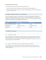
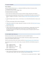
To ground the Base Station Transceiver:
1.
Remove the nut and internal-tooth lock washer from the grounding stud.
2.
Connect a 12 AWG stranded wire with ring lugs from the grounding stud to the building ground.
3.
Reinstall the internal-tooth lock washer and nut, removed earlier, and tighten outer nut to a maximum torque of
65-75 in.·lbs. for the ¼-20 nut.
6.6
CONNECT CURRENT-LIMITING CIRCUIT PROTECTION
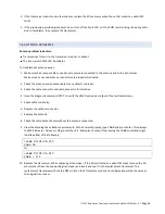
Use current-limiting circuit protection. Current-limiting circuitry must be externally supplied to the Base Station
Transceiver. For installations using fuses or breakers, limits of 15 A for the 24 VDC and 10 A for the 48 VDC version of
the Transceiver are recommended. Follow the manufacturer’s instructions. T he table below describes power supply
requirements, operational ranges, and damage limits for each version.
Table 5 Base Transceiver input power parameters with operational ranges and damage limits
Parameter
24 VDC version
48 VDC version
Nominal DC Power Input Voltage
24 VDC
48 VDC
Operational range
21-27 VDC (+/–12.5%)
42-54 VDC (+/–12.5%)
Damage limit
30 VDC
60 VDC
6.7
CONNECT RF ANTENNAS
6.7.1
ANTENNA PLANNING
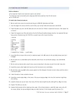
Antenna planning for each site takes place before installation begins. You should already know how many antennas
have been installed at the site. The Base Station Transceiver is designed to be properly terminated to a 50 Ohms
resistance. Base Station Transceivers can have three possible antenna configurations. See
Appendix B— Possible RF
Antenna Configurations
for more information.
6.7.2
CONNECT ANTENNA CABLE(S) FOR NARROWBAND RF ANTENNA(S)
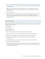
The Base Station Transceiver is rated for 75 W peak envelope power (PEP). Base Station Transceivers have one
combined TX/RX port and two additional ports for receiving only, all of which have Type N female connectors for
narrowband RF antennas.


