ITC 220 Base Station Transceiver Installation Guide PN 133991 Rev. A
| Page 21
6.11
POWER ON THE TRANSCEIVER
Caution
– Power should never be applied to any system unless the user is acutely aware of his intentions and
the environment in which the unit is operating. Applying power to an improperly-terminated radio
transceiver could result in damage to the radio transceiver, cause operator injury, or violate regulatory laws
regarding radio transceiver transmissions as radios will begin transmitting full-rated power without any user
intervention under certain conditions.
To power on the radio transceiver:
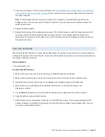
Make sure your computer network card is configured with a fixed IP address of 192.168.255.200. See
Appendix D—
Configure the Computer Ethernet Ports to Communicate with the Transceiver
for more information.
1.
Connect the computer through the MAINT port on the radio transceiver with an Ethernet cable.
2.
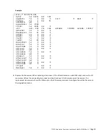
Start an XtermW session.
3.
Confirm that all radio transceiver connections are secure.
4.
Power on the transceiver.
5.
Ensure the breaker did not trip on startup.
Caution
– Take care to not power-cycle the transceiver off and on repeatedly within four minutes of
powering it on. Subjecting the transceiver to three or more successive power cycles within four minutes can
cause a reboot error. If a reboot error occurs, remove power, replace the SD card, and then apply power and
allow the transceiver to boot up normally without power interruptions.
6.11.1
LED DIAGNOSTICS
A blinking PWR (Power) LED on the front panel indicates that the boot sequence has completed. The Ethernet port
connection becomes active within 10 seconds, allowing you to start an
XtermW
session.
The front panel LEDs show the general operational status of the transceiver after it has conducted a POST, which it
does each time it boots up.
Table 6 Front panel LEDs
includes a description of the function of each LED as well as the
color of each LED when the transceiver is functioning properly.
Note:
If a problem occurs
after
the transceiver boots up, the front panel LEDs indicate the problem only after a reboot
of the transceiver (provided the problem persists).
Read the description of each LED carefully. Some LEDs, such as the PWR LED, indicate a problem when they are off.
Other LEDs, such as the FLT (Fault) and SWR, indicate a problem when they are lit. A time-stamped entry will be
displayed onscreen when connected in XtermW whenever the FLT or SWR LEDs are illuminated.


