ITC 220 Base Station Transceiver Installation Guide PN 133991 Rev. A
| Page 22
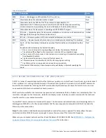
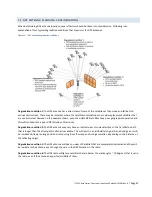
Table 6 Front panel LEDs
Label
Description
Color
PWR
Power — Blinking green LED indicates that the unit is on.
Green
TX
Illuminates when the radio transmitter is keyed.
Red
SWR
Illuminates when the VSWR of the TX port exceeds approximately 3:1.
Illuminates if the TX forward power is not within 25% of the RF output power setting.
(A time-stamped entry specifying the cause will display in the XtermW window.)
Red
RX
Illuminates when the transceiver is receiving a valid 220 MHz PTC signal.
Amber
DTL
DTE Link — Illuminates when the transceiver establishes a connection to a Communication
Manager (CM) through the Ethernet network port.
Amber
RFL
RF Link — Illuminates when an RF link is established between two radios.
Amber
STBY
Standby — Illuminates when the transceiver is in standby mode, indicating TX is disabled.
Red
FLT
Fault — When illuminated, it indicates a variety of fault conditions not indicated by other
LEDs.
Possible faults indicated by the Fault LED include:
One or more internal radio supply voltages are below the minimum threshold.
The extended DC voltage to the transceiver is outside of the acceptable range.
One or more of the transceiver’s internal sensors is indicating a temperature exceeding
the allowable threshold.
The transceiver failed one or more self tests at power on.
TX forward power is not within 25% of the RF output power setting.
The CIM script file is not present or has invalid or corrupt data.
If the Fault LED illuminates, a time-stamped entry will display in XtermW specifying the
cause.
Red
6.11.2
REVIEW THE POWER ON SELF-TEST (POST) RESULTS
A POST is a series of several dozen tests that the transceiver quickly runs on itself, each time it boots up, to determine if
it has a problem or is missing critical information. The radio boots up when it is powered on or the BOOT command is
issued at the command line. Entering the POST command multiple times does not cause the tests to be re-run since
one execution of the tests are automatic at each power on.
POST results show whether the transceiver has passed a test, indicated by PASS, or failed a test, indicated by FAIL. The
results do not appear on the transceiver, which has no display screen. Instead, you send a command to the radio and
view the results on your computer monitor.
To view POST results, remove and reconnect DC power. The transceiver will automatically run internal diagnostics. A
blinking green PWR LED on the front panel indicates that the boot sequence has completed. Within 10 seconds the
Ethernet port becomes active.
Note:
The transmitter is disabled for approximately 30 seconds after power is applied. This delay allows the oven-
controlled oscillator (OCXO) to warm up enough to ensure the accuracy of the transmitter frequency.
Make sure your computer network card has a fixed IP address of 192.168.255.200. See
APPENDIX D — Configure the
Computer Ethernet Ports to Communicate with the Transceiver
for instructions.


